US5686689A - Lightweight composite armor - Google Patents
Lightweight composite armor Download PDFInfo
- Publication number
- US5686689A US5686689A US06/754,932 US75493285A US5686689A US 5686689 A US5686689 A US 5686689A US 75493285 A US75493285 A US 75493285A US 5686689 A US5686689 A US 5686689A
- Authority
- US
- United States
- Prior art keywords
- armor
- ridges
- ceramic body
- ceramic
- composite armor
- Prior art date
- Legal status (The legal status is an assumption and is not a legal conclusion. Google has not performed a legal analysis and makes no representation as to the accuracy of the status listed.)
- Expired - Fee Related
Links
Images

Classifications
-
- F—MECHANICAL ENGINEERING; LIGHTING; HEATING; WEAPONS; BLASTING
- F41—WEAPONS
- F41H—ARMOUR; ARMOURED TURRETS; ARMOURED OR ARMED VEHICLES; MEANS OF ATTACK OR DEFENCE, e.g. CAMOUFLAGE, IN GENERAL
- F41H5/00—Armour; Armour plates
- F41H5/02—Plate construction
- F41H5/023—Armour plate, or auxiliary armour plate mounted at a distance of the main armour plate, having cavities at its outer impact surface, or holes, for deflecting the projectile
-
- F—MECHANICAL ENGINEERING; LIGHTING; HEATING; WEAPONS; BLASTING
- F41—WEAPONS
- F41H—ARMOUR; ARMOURED TURRETS; ARMOURED OR ARMED VEHICLES; MEANS OF ATTACK OR DEFENCE, e.g. CAMOUFLAGE, IN GENERAL
- F41H5/00—Armour; Armour plates
- F41H5/02—Plate construction
- F41H5/04—Plate construction composed of more than one layer
- F41H5/0414—Layered armour containing ceramic material
- F41H5/0421—Ceramic layers in combination with metal layers
Definitions
- the present invention relates generally to ballistic armor, and more particularly to a lightweight composite armor.
- lightweight protective armor plates including a composite armor plate having a metallic backing plate to which square plate members or tiles made of a ceramic material are attached. The tiles are arranged in a matrix pattern.
- U.S. Pat. No. 3,616,115 Klimmek
- another lightweight composite armor plate including successive layers of small discrete ceramic blocks is disclosed. The blocks are encapsulated within a metal matrix by solid state diffusion bonding so that residual stress effects from the bonding step prestress the blocks in compression to make the blocks more shatter resistant.
- a composite shock resisting body which is inwardly formed around ceramic blocks laid out in a matrix pattern is also disclosed in U.S. Pat. No. 3,874,855 (Legrand).
- U.S. Pat. No. 3,859,892 Disclosed in U.S. Pat. No. 3,859,892 (Coes) is a composite ceramic armor which includes a laminated fiberglass backing. When the ceramic fails after being struck by a projectile, the laminated glass cloth backing dissipates the energy delivered to protect personnel behind the armor. The backing is preferably extended over the edge of the plate to provide extra protection along the free edge of the plate.
- U S. Pat. No. 3,592,952 Hauck
- a composite ceramic armor including a ceramic tile which is attached to a backing element having side lips or flanges is disclosed.
- a ballistic shield including a blanket portion is disclosed.
- a plurality of ceramic tiles are bonded to the blanket portion around the fronts of the tiles and a metal backing plate is provided along the backs of the tiles.
- the general attachment of ceramic tiles having a backing of glass fibers for use as a surface covering for a wall or the like using a suitable mastic or other cement is disclosed in U.S. Pat. No. 2,878,666 (Drummond).
- a rigid armor wall element having an impact surface provided with alternate peaks and valleys is also disclosed in U.S. Pat. No. 3,636,895 (Kelsey).
- the wall element includes integral reinforcing means such as ribs which extend outwardly from the front of the wall.
- a lightweight composite armor in accordance with the present invention, includes an integrally formed matrix block which has a generally planar back and a plurality of intersecting ridges extending from a front side of the planar back. The ridges terminate in a top and form a matrix of open-topped cells in the matrix block.
- An energy absorbing ceramic body is located in each cell. The ceramic body serves as a primary energy-absorbent for the armor as each ceramic body is maintained in the associated cell.
- Individual front plates close the open top of each associated cell in mating contact with the ceramic body.
- An attaching means is provided for attaching each front plate to the tops of adjacent ridges of the cells around the periphery of the front plates. When impacted by a projectile on one of the front plates, any damage is substantially limited to that one front plate and the underlying ceramic body leaving the remaining armor substantially undamaged.
- the ceramic body is made either integrally formed or from at least two pieces.
- the ceramic body can also be made of an alumina ceramic or a hot-pressed silicon carbide ceramic.
- the matrix block and front plate can be formed of an aluminum alloy or of a hard steel alloy.
- fillets are provided at the juncture between the planar back and the ridges as well as at the juncture between the ridges.
- the front plates preferably include an upstanding flange around the periphery thereof so that the attaching means attaches the flanges of the front plates to the ridges.
- the attaching means is a weld.
- a ceramic-based grout is also preferably located in these gaps to fill these gaps.
- the ceramic body preferably also includes a recessed surface, such as a concave surface, adjacent the mating front plate. This induces particles resulting from an impact to follow a path away from the front plate to localize any damage in the area of the associated cells.
- a momentum trap means can be attached to the rear side of the planar back for trapping spall ejected from the planar back as a result of a projectile impact on the armor.
- the momemtum trap is a layer of a flexible material, such as a polymer impregnated woven fabric.
- the rear side of the planar back can also be provided with stiffening ridges to increase the strength of the planar back if desired.
- FIG. 1 is a top plan view of a composite armor according to the present invention.
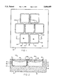
- FIG. 2 is a cross-sectional side elevation view of the armor depicted in FIG. 1 taken along the line 2--2.
- FIG. 3 is a cutaway perspective view of a modified armor according to the present invention.
- FIG. 4 is a cross-sectional side view of the modified form of the invention depicted in FIG. 3.
- FIG. 5 is a cross-sectional side view of another modified form of the present invention.
- Composite armor 10 includes a matrix block 12.
- Matrix block 12 is formed of a suitable metal, such as an aluminum alloy or a hard steel alloy.
- Matrix block 12 includes a generally planar back 14 having a front 16 and a rear 18. Upstanding from front 16 is a plurality of intersecting ridges 20 which are integrally formed with planar back 14. As shown, intersecting ridges 20 form a pattern of open-topped cells 22.
- each cell 22 Located in each cell 22 is a ceramic body 24. Ceramic materials have been shown to have a high energy absorbing capability in comparison with more conventional materials such as metals. In addition, ceramics have lower densities than many metals, so that their use can be advantageous when light weight is a goal of the armor design. In order to take maximum advantage of the energy absorbing capability of the ceramic, it is a specific feature of the present invention that each ceramic body 24 is confined to a specific cell 22. In this manner, each ceramic body 24 is held in place so that upon impact by a projectile, that ceramic body 24 absorbs the kinetic energy of the projectile with little or no damage to the adjacent ridges 20 and planar back 14 and hence without damage to the rest of armor 10.
- each ceramic body 24 preferably includes a recessed front such as concave front surface 26.
- Concave front surface 26 induces particles resulting from impact to follow a path away from the front surface so that these particles do not cause severe damage to an adjacent cell 22 of armor 10.
- ceramic bodies 24 are made of an alumina ceramic or a hot-pressed silicon carbide ceramic depending on the particular application of armor 10.
- Matrix block 12 also includes fillets 28 located at the intersection of planar back 14 and ridges 20.
- fillets 30 are also provided at the intersection of ridges 20.
- ceramic body 24 is designed to fit matingly in cells 22. However, if gaps 32 unavoidably exist between cells 22 and the associated ceramic body 24, a ceramic-based grout 34 such as Sauereisen cement is provided in gaps 32. This provides ceramic body 24 with a tight fit in the associated cell 22. It should be appreciated that the tight fit of ceramic body 24 in cell 22 maximizes the energy absorbing capabilities of ceramic body 24.
- front plate 36 Located above each ceramic body 24 in each cell 22 is a front plate 36. As shown best in FIG. 2, front plate 36 has a rear surface which matingly abuts concave front surface 26 of ceramic body 24. In addition, front plate 36 includes an upstanding flange 38 around the periphery of front plate 36. Flange 38 is attached to ridges 20 of cell 22 by a suitable attaching means such as a weld 40. Flange 38 is designed to be a snug fit in the top of cell 22 and is preferably made out of the same material as matrix block 12.
- FIGS. 3 and 4 Depicted in FIGS. 3 and 4 is an alternative embodiment of a composite armor 50 according to the present invention.
- Composite armor 50 is similar to composite armor 10 and the similar elements of composite armor 50 have been identified with the same numerals used to identify the elements in composite armor 10 but with the addition of a "'" after the numeral.
- composite armor 50 does differ from composite armor 10 somewhat in that ceramic bodies 24' do not have a concave front surface 26 but rather have a flat front surface as shown.
- Front plates 36' are similarly flat shaped. The shape of ceramic bodies 24' and front plate 36' simplifies the construction of ceramic bodies 24' and front plate 36' compared to ceramic bodies 24 and front plate 36. However, the inducement of particles resulting from an impact to follow a path away from the front surface of armor 50 is not as great as when a concave front surface 26 is used.
- Composite armor 50 also includes a momentum trap means 52 which is preferably a layer of flexible material such as a polymer impregnated woven fabric.
- a suitable impregnated woven fabric is a phenolic resin impregnated KEVLAR fabric.
- Momentum trap means 52 is attached to rear 18' of planar back 14' by a steel frame 56 and cap screws 58 received in matrix block 12' as shown.
- Momentum trap means 52 is designed to provide additional momentum loading capacity for composite armor 50.
- Momentum trap means 52 is especially effective in trapping spall ejected from rear 18' of planar back 14'.
- Composite armor 70 includes a matrix block 72 having a planar back 74 and ridges 76 forming cells 78.
- a ceramic body 80 is provided which comprises two mating ceramic blocks 82.
- a ceramic body 84 is provided which comprises three ceramic blocks 86.
- Ceramic bodies 80 and 84 are conveniently used where a single preformed ceramic body, such as ceramic body 24, is unavailable.
- a plurality of ceramic blocks can be used in some cases where improved performance results compared to a single preformed ceramic body.
- the mating blocks can have their mating surfaces at any orientation such as horizontal or at a slanted angle instead of the vertical mating surfaces depicted.
- planar back 74 of composite armor 70 has an increased stiffness provided by ridges 88 protruding from the rear of planar back 74. It should be appreciated that the increased stiffness of ridges 88 can be provided with no change in the areal density of composite armor 70 relative to a composite armor without ridges 88. In order to accomplish this, the thickness of planar block 74 is decreased by the amount of material needed to create ridges 88. This redistribution of the material increases the moment of inertia of the cross section at intervals across the plane of planar back 74 in a manner similar to a honeycomb structure.
- planar back 74 The stiffness of planar back 74 is important because if planar back 74 lacks sufficient stiffness, planar back 74 may deflect easily under any applied momentum load so as to allow rapid displacement of ceramic block fragments. This displacement, which represents a loss of confinement of the ceramic block material, results in a reduction of the energy absorbing capability of the ceramic block. In addition, a lack of sufficient stiffness will also result in undesired deflection over a much wider area of armor 70 so that the performance of more than just the impacted area of cell 78 is affected. It should also be appreciated that while the stiffening of planar back 74 is desirable, planar back 74 must still retain some energy absorption capability of its own. Therefore, the amount of material used to form ridges 88 must not be so great as to leave the remaining portion of planar back 74 too thin.
- a multi-layer type is provided with a ceramic material constituting an intermediate layer confined between front and back plates made of metal. Fabrication is designed to be accomplished by conventional machining and forming techniques.
- the cells of the present invention subdivide the ceramic core material into separate compartments.
- the cells of the present invention have been depicted as being square or rectangular in shape, it should be appreciated that any practical shape which allows uniform distribution across the surface is possible.
- shapes as circles, triangles, hexagons, and octagons could be used, both in place of regular rectangular cells or in combination with such cells.
- rectangular or triangular cells such cells can be either in the staggered row configuration depicted in FIG. 1 or in unstaggered rows and columns.
- each cell has an individual front plate which provides frontal confinement for the ceramic body underneath. Because each front plate is separate and retained at the edges, each front plate reacts to an impact independently. Thus, the lateral spread of a front plate damage is limited. In contrast, a continuous front plate covering many cells can peel away as a result of a single impact and thus seriously reduce the ceramic body confinement of many cells.
- the ceramic body is designed with a sufficient thickness to contain a major portion of any projectile kinetic energy.
- the performance of a ceramic body is degraded if the fit of the body within a cell is too loose.
- the tolerances necessary to retain satisfactory performance of a ceramic body should be easily met by routine fabrication methods.
- the fit and hence the performance can be improved if gaps are filled with a ceramic-based grout. If a grout is used, the grout must also be able to withstand any local heating that occurs when the front plates are welded in place.
- planar back of the present invention is designed to be the main structural element of the armor of the present invention.
- the planar back also provides additional energy absorbing capacity. It should be appreciated that the ridges provided on the front of the planar back also stiffen the planar back as well as holding the front plate to the planar back.
- fillets as described above is also designed to reduce stress concentrations. Since the juncture of the ridges and planar back as well as the juncture of the ridges are the points which are highly loaded when the armor is impacted, it is important that these points be as strong as possible and resistant to failure by shear. Properly designed fillets provide this needed strength.
- the flange provided on the front plate is preferably machined on so as to provide additional in-plane stiffening as well as a supporting surface for the welded attachment to the ridges.
- the welding of the flanges to the ridges is also designed to promote breakaway of an impacted plate while providing sufficient strength to limit damage to adjacent cells.
- This experiment was designed to test a lightweight armor as protection against steel core bullets.
- Many combat vehicles currently utilize monolithic aluminum armor as an element in their structure to afford protection against typical threats of this type such as rifle or machine gun launched armor piercing bullets.
- Such vehicles include a variety of naval vessels, amphibious landing craft, and armored troop carriers.
- Armored portions include hulls, superstructures, turrets, and protective skirts.
- a typical combat situation involves the need to defend against 12.7 mm, steel core, armor piercing bullets.
- the most severe test of an armor against this type of threat is characterized by an impact at muzzle velocity (about 0.82 km/sec) and normal (0°) obliquity. Under these conditions, monolithic aluminum armor approximately 83 mm thick and weighing 220 kg/m 2 is required to provide adequate protection.
- a composite armor as depicted in FIGS. 1 and 2 was tested. The cells had a 61 mm length and width, a 16.5 mm thickness at the center, ridges which were 3.2 mm thick, and 6 mm radius corners.
- the thickness of the front plate at the center was 6.9 mm while the thickness of the planar back was 23 mm.
- the radius of the concave surface of the ceramic body was 76 mm and the heighth of the flange above the front plate was 3.2 mm.
- This composite armor had a weight of 146 kg/m 2 , which is only 67% of the weight of the monolithic aluminum required to defeat this same threat.
- the matrix block was formed of an aluminum alloy (6061-T651) and the ceramic bodies were formed of alumina ceramic (SC-98D manufactured by Centerflex Technologies Inc.).
- the test armor according to the present invention is similar to that depicted in FIG. 3, but without the momentum trap means at the back.
- the ceramic body did not have a concave front surface similar to the armor depicted in FIG. 2.
- the cell of this armor had a width and length of 74.7 mm, a thickness of 30.6 mm, and rounded edges of 6 mm radius.
- the thickness of the front plate was 3.99 mm with a total height of the plate being 5.0 mm.
- the thickness of the planar back was 22.7 mm so that the armor had a total height of 58.4 mm.
- the flange of the front plate had a thickness of 3.18 mm and the thickness of the ridges was 4.78 mm.
- the ceramic body was a hot-pressed silicon carbide (Ceralloy 146 IG manufactured by Ceradyne Inc.) and the matrix block was made from an aluminum alloy (6061-T651).
- This armor had an areal density of 166 kg/m 2 , only 48% of the weight of the required monolithic aluminum armor.
- an armor designed according to the present invention was capable of defeating multiple impacts of a 14.5 mm, tungsten carbide core bullet of the BS41 type at a weight approximately one-half that of the required monolithic aluminum armor.
- the need to armor a portion of a combat vehicle may not permit the complete replacement of an existing structural plate or element. This can be true especially when the existing structure also serves an armor function but is found to be inadequate against improved threats.
- one solution is the addition of a supplemental armor layer or applique in front of the existing armor.
- applique adds unwanted weight to the vehicle, so it is of utmost importance that applique weights be kept to a minimum.
- a ceramic composite armor designed according to the present invention is ideal for this purpose.
- the armor tested was designed as a supplement to the monolithic aluminum armor used on the lower glacis of the U.S. Bradley fighting vehicle.
- the lower glacis as built consists of 52 mm of 7039 aluminum at a minimum obliquity of 45° to the expected line of fire.
- an advanced threat such as the U.S. heavy metal core M-791, this armor by itself is inadequate.
- the M-791 can penetrate over 51 mm of steel armor or approximately 145 mm of aluminum armor at 45° and a muzzle velocity of 1.45 km/sec.
- the basic design of the applique tested is similar to that disclosed in FIG. 3 but without the momentum trap means.
- the cells used were rectangular having a width of 76 mm and a length of 108 mm.
- the thickness of the ceramic block was 27.9 mm with 6 mm radius corners.
- the thickness of the front plate was 2.5 mm while the thickness of the planar back was 22.9 mm.
- the thickness of the ridges was 4.8 mm along the width direction between the cells and 6 mm along the length direction of the cells.
- the total thickness of the armor was 57.2 mm.
- the matrix block was made of cast A357 aluminum alloy and the ceramic core was 146IG hot-pressed silicon carbide.
- the applique design weighed 158 kg/m 2 while the 52 mm of 7039 aluminum glacis armor weighs 142 kg/m 2 .
- the total areal density for the combination is 300 kg/m 2 .
- Relative to 51 mm of steel weighing 408 kg/m 2 there is a weight savings of 26%.
- Relative to 145 mm of aluminum weighing 391 kg/m 2 the savings is 23%.
- Heavy armor is typified by thick steel plates used for portions of tank bodies and large gun turrets. Because of the magnitude of the threats involved, extremely thick steel plates are required. For example, the U.S. M-774, heavy metal, long rod projectile can penetrate approximately 200 mm of rolled homogenous steel armor at 60° obliquity and 1.50 km/sec velocity. This armor weighs 1565 kg/m 2 . The very large fraction of a vehicle's total weight devoted to such armor places an extreme limitation on performance expectations. Therefore, it is highly desirable to seek ways of reducing the weight of the armor without reducing the level of protection.
- the composite armor tested according to the present invention was similar to that depicted in FIG. 4 and included the momentum trap means provided at the back of the planar back.
- the ceramic body had a square cross section of 45 mm and a height of 33.5 mm.
- the thickness of the front plate was 2.5 mm while the thickness of the planar back was 5.1 mm.
- the total height of the armor, exclusive of the momentum trap means, was 45.9 mm.
- the thickness of the momentum trap means was 8.0 mm, and the thickness of the ridges was 3.2 mm.
- the matrix block and front plates were made of 4340 steel alloy heat treated to a Brinell hardness number of 300.
- the ceramic bodies were formed of a hot-pressed silicon carbide ceramic (146 IG).
- the momentum trap means was a phenolic resin impregnated KEVLAR fabric.
- the weight of this armor is 208 kg/m 2 , or only 52% of a required steel armor.
- the test condition for this armor simulated conditions which might be encountered by the glacis or turret of a battle tank in combat.
- the projectile was a long rod having a fineness ratio of 10 and a weight of 65 gm. It was made of a depleted uranium (DU) alloy. The impact occurred at a velocity of approximately 1.52 km/sec at 60° obliquity. Under these conditions, this projectile can penetrate 51 mm of rolled homogenous steel armor weighing 397 kg/m 2 .
- the armor described above was struck twice by the DU long rod projectiles described above at the locations indicated by arrows A and B in FIG. 4. These impact points were chosen so that each trajectory passed through the center of mass of the corresponding ceramic body.
- the impact velocities were 1.51 and 1.48 km/sec, respectively.
- the spacing of the impact trajectors was less than 6 projectile diameters.
- a specimen target of a ceramic composite armor system designed according to the present invention can provide projectile protection against multiple impacts of a heavy metal, high fineness-ratio projectile for a weight per unit area (areal density) of approximately one-half that of the necessary monolithic steel armor.
- the jet of a shaped charged warhead can exceed that of other weapon systems of comparable scale.
- the extremely heavy weight of monolithic armor required in combat vehicles to provide protection against such jets suggests that lighter alternatives are desired.
- a ceramic composite armor according to the present invention was tested against shaped charges of this type.
- the tested armor was intended to provide protection against multiple impacts of the jet from a 28 mm diameter shaped charge at 60° obliquity.
- Such a charge is capable of penetrating 155 mm of rolled homogeneous steel armor.
- the required armor weighed 606 kg/m 2 .
- the weight was 262 kg/m 2 representing a weight savings of 57%.
- the shaped charge and target tested were approximately one-fifth the size of a full-scale weapon and armor.
- the ceramic armor tested according to the present invention was similar to that depicted in FIG. 4.
- Square cross-sectioned ceramic blocks having a width of 119 mm and a thickness of 48.1 mm were used.
- the front plates had a thickness of 1.9 mm while the planar back had a thickness of 9.8 mm.
- the thickness of the ridges was 4.8 mm.
- the total thickness of the armor without the momentum trap means was 64.3 mm while the thickness of the momentum trap means was 7.4 mm.
- the ceramic bodies to be impacted were made of a hot-pressed silicon carbide (146IG) while the remaining ceramic bodies were made of sintered aluminum oxide (SC-98D).
- the limited use of hot-pressed silicon carbide ceramic bodies was based on the consideration of the relative cost of the two ceramics.
- the matrix block and front plates were made of 4340 steel alloy heat treated to a Brinell hardness of 300.
- the momentum trap means was a KEVLAR backup layer such as described above.
- the above armor design was struck by a jet from a 28 mm shaped charge device at each of the hot-pressed silicon carbide ceramic bodies.
- the jet was directed at 60° obliquity toward the center of each ceramic body.
- the nominal jet velocity was 8.5 km/sec and the spacing of the two impact points was equivalent to three times the bore diameter of a hypothethical launcher for the 28 mm device.
- a ceramic composite armor system according to the present invention can be effective in protecting against multiple impacts of a shaped charged jet for a weight that is less than one-half that of a required monolithic steel armor.
Abstract
Description
Claims (21)
Priority Applications (1)
| Application Number | Priority Date | Filing Date | Title |
|---|---|---|---|
| US06/754,932 US5686689A (en) | 1985-05-17 | 1985-05-17 | Lightweight composite armor |
Applications Claiming Priority (1)
| Application Number | Priority Date | Filing Date | Title |
|---|---|---|---|
| US06/754,932 US5686689A (en) | 1985-05-17 | 1985-05-17 | Lightweight composite armor |
Publications (1)
| Publication Number | Publication Date |
|---|---|
| US5686689A true US5686689A (en) | 1997-11-11 |
Family
ID=25036999
Family Applications (1)
| Application Number | Title | Priority Date | Filing Date |
|---|---|---|---|
| US06/754,932 Expired - Fee Related US5686689A (en) | 1985-05-17 | 1985-05-17 | Lightweight composite armor |
Country Status (1)
| Country | Link |
|---|---|
| US (1) | US5686689A (en) |
Cited By (68)
| Publication number | Priority date | Publication date | Assignee | Title |
|---|---|---|---|---|
| US5996115A (en) * | 1992-08-24 | 1999-12-07 | Ara, Inc. | Flexible body armor |
| US6009789A (en) * | 1997-05-01 | 2000-01-04 | Simula Inc. | Ceramic tile armor with enhanced joint and edge protection |
| US6345563B1 (en) * | 2000-06-30 | 2002-02-12 | United Defense, L.P. | Reactive pill armor |
| US6532857B1 (en) * | 2000-05-12 | 2003-03-18 | Ceradyne, Inc. | Ceramic array armor |
| US6745662B2 (en) | 2001-08-06 | 2004-06-08 | The United States Of America As Represented By The Administrator Of The National Aeronautics And Space Administration | Cross cell sandwich core |
| US20050188825A1 (en) * | 2003-07-31 | 2005-09-01 | Blast Gard International | Explosive effect mitigated containers |
| US20050193480A1 (en) * | 2003-04-15 | 2005-09-08 | Carlson Richard A. | Energy absorbing device for ballistic body armor |
| US20050217471A1 (en) * | 2003-11-25 | 2005-10-06 | Sgl Carbon Ag | Ceramic antiballistic layer, process for producing the layer and protective device having the layer |
| US20050242093A1 (en) * | 2003-07-31 | 2005-11-03 | Blast Gard International | Explosive effect mitigated containers and enclosing devices |
| US6969548B1 (en) | 1999-08-30 | 2005-11-29 | Goldfine Andrew A | Impact absorbing composite |
| US7104177B1 (en) * | 2000-01-11 | 2006-09-12 | Aghajanian Michael K | Ceramic-rich composite armor, and methods for making same |
| US20070028759A1 (en) * | 2004-06-15 | 2007-02-08 | Williams Charles A | Vehicle armor system |
| US20070138157A1 (en) * | 2005-12-20 | 2007-06-21 | Metal Improvement Company Llc | Laser Shock Processing With Momentum Trap |
| US7273903B2 (en) | 2000-08-11 | 2007-09-25 | E.I. Du Pont De Nemours And Company | Bi-modal ionomers |
| US7322267B1 (en) | 2004-06-15 | 2008-01-29 | Foi Group, Llc | Enhanced light weight armor system with reactive properties |
| US7350450B1 (en) * | 2006-09-18 | 2008-04-01 | Battelle Energy Alliance, Llc | Armor structures |
| US20080105114A1 (en) * | 2003-07-30 | 2008-05-08 | The Boeing Company | Composite containment of high energy debris and pressure |
| US7389718B1 (en) | 2005-09-23 | 2008-06-24 | Carter Gerald D | Ballistic blanket |
| US20080271595A1 (en) * | 2006-04-20 | 2008-11-06 | Bird Connie E | Lightweight projectile resistant armor system |
| US20080307953A1 (en) * | 2006-07-20 | 2008-12-18 | Dynamic Defense Materials, Llc | Encapsulated ballistic structure |
| US20090072569A1 (en) * | 2007-09-17 | 2009-03-19 | Engelbart Roger W | Methods and systems for fabrication of composite armor laminates by preform stitching |
| US20090114083A1 (en) * | 2006-01-23 | 2009-05-07 | Moore Iii Dan T | Encapsulated ceramic composite armor |
| WO2009061539A2 (en) * | 2007-08-15 | 2009-05-14 | University Of Virginia Patent Foundation | Synergistically-layered armor systems and methods for producing layers thereof |
| US7546795B1 (en) | 2004-06-15 | 2009-06-16 | Foi Group, Inc. | Enhanced light weight armor system with deflective operation |
| US20090151550A1 (en) * | 2007-12-14 | 2009-06-18 | Israel Stol | Concepts for Weldable Ballistic Products for Use in Weld Field Repair and Fabrication of Ballistic Resistant Structures |
| WO2009091373A2 (en) * | 2007-10-10 | 2009-07-23 | Hardwire Llc | Armor panel system |
| WO2009151426A1 (en) * | 2008-05-27 | 2009-12-17 | Force Protection Technologies, Inc. | Apparatus for defeating high energy projectiles |
| US20090320675A1 (en) * | 2007-04-23 | 2009-12-31 | Landingham Richard L | Mosaic Transparent Armor |
| US20100077911A1 (en) * | 2008-05-05 | 2010-04-01 | Gigi Simovich | Ballistic plate and method of fabrication thereof |
| US20100083819A1 (en) * | 2007-07-24 | 2010-04-08 | Thomas Mann | Armor system |
| US20100089228A1 (en) * | 2006-08-15 | 2010-04-15 | Scott Brian R | Composite armor with a cellular structure |
| US20100196671A1 (en) * | 2009-02-02 | 2010-08-05 | 3M Innovative Properties Company | Polymeric composite article and method of making the same |
| US7770506B2 (en) | 2004-06-11 | 2010-08-10 | Bae Systems Tactical Vehicle Systems Lp | Armored cab for vehicles |
| US20100212484A1 (en) * | 2007-09-26 | 2010-08-26 | Williams Raymond F | Method and apparatus for changing the trajectory of a projectile |
| US20110023697A1 (en) * | 2006-05-01 | 2011-02-03 | Warwick Mills, Inc. | Mosaic extremity protection system with transportable solid elements |
| US7895932B1 (en) * | 2006-11-14 | 2011-03-01 | D&O Innovations, LLC | Optically clear turret dome, and combined turret shroud |
| US20110174143A1 (en) * | 2007-09-28 | 2011-07-21 | Sanborn Steven L | Apparatus, methods and system for improved lightweight armor protection |
| US20110180279A1 (en) * | 2010-01-24 | 2011-07-28 | Lehavot Fire Protection Ltd. | Device and method of protecting a fire extinguisher |
| US20110214561A1 (en) * | 2008-11-04 | 2011-09-08 | Gigi Simovich | Method and a device for pre-stressed armor |
| US20110239348A1 (en) * | 2008-02-14 | 2011-10-06 | Warrior Sports, Inc. | Protective covering |
| US20120055327A1 (en) * | 2006-04-20 | 2012-03-08 | Holowczak John E | Armor system having ceramic matrix composite layers |
| US8193283B2 (en) | 2000-08-11 | 2012-06-05 | E. I. Du Pont De Nemours And Company | Golf balls with soft, resilient bimodal ionomeric covers |
| RU2469255C1 (en) * | 2011-04-26 | 2012-12-10 | Открытое акционерное общество "Центральный научно-исследовательский технологический институт "Техномаш" (ОАО "ЦНИТИ "Техномаш") | Composite armor |
| WO2013006008A2 (en) * | 2011-07-06 | 2013-01-10 | 아주대학교산학협력단 | Defense structure for national defense |
| EP2003418A3 (en) * | 2007-06-14 | 2013-02-20 | Oto Melara S.p.A. | Reinforcement and armouring panel for a vehicle |
| US8524023B2 (en) | 2007-09-17 | 2013-09-03 | The Boeing Company | Methods and systems for fabrication of composite armor laminates by preform stitching |
| US8546915B2 (en) | 2011-02-07 | 2013-10-01 | GLOBLFOUNDRIES, Inc. | Integrated circuits having place-efficient capacitors and methods for fabricating the same |
| US20140033908A1 (en) * | 2012-07-31 | 2014-02-06 | Spokane Industries | Encapsulated Preformed Shapes |
| US8689671B2 (en) | 2006-09-29 | 2014-04-08 | Federal-Mogul World Wide, Inc. | Lightweight armor and methods of making |
| US8720314B2 (en) | 2007-09-17 | 2014-05-13 | The Boeing Company | Methods and systems for fabrication of composite armor laminates by preform stitching |
| US20140134453A1 (en) * | 2003-05-07 | 2014-05-15 | Microfabrica Inc. | Multi-Layer, Multi-Material Micro-Scale and Millimeter-Scale Devices with Enhanced Electrical and/or Mechanical Properties |
| US20140260943A1 (en) * | 2013-03-18 | 2014-09-18 | Sarsilmaz Silah Sanayi A.S. | Submachine gun |
| US8869673B2 (en) | 2006-01-31 | 2014-10-28 | Sikorsky Aircraft Corporation | Structural panel with ballistic protection |
| US20150061182A1 (en) * | 2010-04-12 | 2015-03-05 | The Government Of The Us, As Represented By The Secretary Of The Navy | Method for forming cylindrical armor elements |
| US9097496B2 (en) | 2006-04-20 | 2015-08-04 | Sikorsky Aircraft Corporation | Lightweight projectile resistant armor system with surface enhancement |
| US9222260B1 (en) | 2009-04-10 | 2015-12-29 | Su Hao | Lightweight multi-layer arch-structured armor (LMAR) |
| US9366506B2 (en) | 2012-09-19 | 2016-06-14 | Aps Materials, Inc. | Coated ballistic structures and methods of making same |
| US9658033B1 (en) * | 2012-05-18 | 2017-05-23 | Armorworks Enterprises LLC | Lattice reinforced armor array |
| WO2019038720A1 (en) | 2017-08-23 | 2019-02-28 | Agp America S.A. | Transparent multi-hit armor |
| CN110274521A (en) * | 2018-11-22 | 2019-09-24 | 无锡银邦防务科技有限公司 | A kind of composite material and preparation method |
| US10641792B2 (en) | 2003-12-31 | 2020-05-05 | University Of Southern California | Multi-layer, multi-material micro-scale and millimeter-scale devices with enhanced electrical and/or mechanical properties |
| US20200166314A1 (en) * | 2017-07-19 | 2020-05-28 | Kennametal Inc. | Armor plate and armor consisting of carrier and armor plate |
| US10877067B2 (en) | 2003-02-04 | 2020-12-29 | Microfabrica Inc. | Pin-type probes for contacting electronic circuits and methods for making such probes |
| US20210341262A1 (en) * | 2018-08-05 | 2021-11-04 | Gigi Simovitch | Armor and method of manufacture |
| US11262383B1 (en) | 2018-09-26 | 2022-03-01 | Microfabrica Inc. | Probes having improved mechanical and/or electrical properties for making contact between electronic circuit elements and methods for making |
| US11865809B2 (en) * | 2019-08-22 | 2024-01-09 | The Boeing Company | Method for forming non-bonded regions in multi-layered metallic armor |
| WO2023211658A3 (en) * | 2022-04-05 | 2024-02-15 | Firstspear Technology Group, Llc | Ballastic plate carrier |
| US11906273B2 (en) | 2019-06-13 | 2024-02-20 | Kennametal Inc. | Armor plate, armor plate composite and armor |
Citations (7)
| Publication number | Priority date | Publication date | Assignee | Title |
|---|---|---|---|---|
| US1215727A (en) * | 1915-11-06 | 1917-02-13 | John Slattery | Heat-resisting structural material and process of making same. |
| FR70689E (en) * | 1956-07-11 | 1959-06-05 | Sambre & Meuse Usines | Improvements to shielding |
| US3324768A (en) * | 1950-05-22 | 1967-06-13 | Robert J Eichelberger | Panels for protection of armor against shaped charges |
| US3616115A (en) * | 1968-09-24 | 1971-10-26 | North American Rockwell | Lightweight ballistic armor |
| US3715999A (en) * | 1971-05-18 | 1973-02-13 | Shwayder Chem & Metallurg Corp | Drill proof plates |
| US3793648A (en) * | 1971-12-17 | 1974-02-26 | Feldmuehle Anlagen Prod | Bullet-resisting armor |
| US3874855A (en) * | 1969-07-22 | 1975-04-01 | Cegedur Gp | Composite shock resisting bodies |
-
1985
- 1985-05-17 US US06/754,932 patent/US5686689A/en not_active Expired - Fee Related
Patent Citations (7)
| Publication number | Priority date | Publication date | Assignee | Title |
|---|---|---|---|---|
| US1215727A (en) * | 1915-11-06 | 1917-02-13 | John Slattery | Heat-resisting structural material and process of making same. |
| US3324768A (en) * | 1950-05-22 | 1967-06-13 | Robert J Eichelberger | Panels for protection of armor against shaped charges |
| FR70689E (en) * | 1956-07-11 | 1959-06-05 | Sambre & Meuse Usines | Improvements to shielding |
| US3616115A (en) * | 1968-09-24 | 1971-10-26 | North American Rockwell | Lightweight ballistic armor |
| US3874855A (en) * | 1969-07-22 | 1975-04-01 | Cegedur Gp | Composite shock resisting bodies |
| US3715999A (en) * | 1971-05-18 | 1973-02-13 | Shwayder Chem & Metallurg Corp | Drill proof plates |
| US3793648A (en) * | 1971-12-17 | 1974-02-26 | Feldmuehle Anlagen Prod | Bullet-resisting armor |
Cited By (112)
| Publication number | Priority date | Publication date | Assignee | Title |
|---|---|---|---|---|
| WO2001051878A1 (en) * | 1992-08-24 | 2001-07-19 | Ara, Inc. | Flexible body armor |
| US5996115A (en) * | 1992-08-24 | 1999-12-07 | Ara, Inc. | Flexible body armor |
| US6009789A (en) * | 1997-05-01 | 2000-01-04 | Simula Inc. | Ceramic tile armor with enhanced joint and edge protection |
| US6332390B1 (en) | 1997-05-01 | 2001-12-25 | Simula, Inc. | Ceramic tile armor with enhanced joint and edge protection |
| US6969548B1 (en) | 1999-08-30 | 2005-11-29 | Goldfine Andrew A | Impact absorbing composite |
| US7104177B1 (en) * | 2000-01-11 | 2006-09-12 | Aghajanian Michael K | Ceramic-rich composite armor, and methods for making same |
| US6532857B1 (en) * | 2000-05-12 | 2003-03-18 | Ceradyne, Inc. | Ceramic array armor |
| US6345563B1 (en) * | 2000-06-30 | 2002-02-12 | United Defense, L.P. | Reactive pill armor |
| US8410220B2 (en) | 2000-08-11 | 2013-04-02 | E I Du Pont De Nemours And Company | Golf balls with soft, resilient bimodal ionomeric covers |
| US8193283B2 (en) | 2000-08-11 | 2012-06-05 | E. I. Du Pont De Nemours And Company | Golf balls with soft, resilient bimodal ionomeric covers |
| US7273903B2 (en) | 2000-08-11 | 2007-09-25 | E.I. Du Pont De Nemours And Company | Bi-modal ionomers |
| US6745662B2 (en) | 2001-08-06 | 2004-06-08 | The United States Of America As Represented By The Administrator Of The National Aeronautics And Space Administration | Cross cell sandwich core |
| US10877067B2 (en) | 2003-02-04 | 2020-12-29 | Microfabrica Inc. | Pin-type probes for contacting electronic circuits and methods for making such probes |
| US20050193480A1 (en) * | 2003-04-15 | 2005-09-08 | Carlson Richard A. | Energy absorbing device for ballistic body armor |
| US6961957B2 (en) | 2003-04-15 | 2005-11-08 | Safari Land Ltd., Inc. | Energy absorbing device for ballistic body armor |
| US20140134453A1 (en) * | 2003-05-07 | 2014-05-15 | Microfabrica Inc. | Multi-Layer, Multi-Material Micro-Scale and Millimeter-Scale Devices with Enhanced Electrical and/or Mechanical Properties |
| US9671429B2 (en) * | 2003-05-07 | 2017-06-06 | University Of Southern California | Multi-layer, multi-material micro-scale and millimeter-scale devices with enhanced electrical and/or mechanical properties |
| US10215775B2 (en) | 2003-05-07 | 2019-02-26 | University Of Southern California | Multi-layer, multi-material micro-scale and millimeter-scale devices with enhanced electrical and/or mechanical properties |
| US20080105114A1 (en) * | 2003-07-30 | 2008-05-08 | The Boeing Company | Composite containment of high energy debris and pressure |
| US20100095832A1 (en) * | 2003-07-30 | 2010-04-22 | The Boeing Company | Composite containment of high energy debris and pressure |
| US7597040B2 (en) | 2003-07-30 | 2009-10-06 | The Boeing Company | Composite containment of high energy debris and pressure |
| US7954418B2 (en) | 2003-07-30 | 2011-06-07 | The Boeing Company | Composite containment of high energy debris and pressure |
| US20070006723A1 (en) * | 2003-07-31 | 2007-01-11 | Waddell John L Jr | Acoustic shock wave attenuating assembly |
| US7343843B2 (en) | 2003-07-31 | 2008-03-18 | Blast Gard International | Explosive effect mitigated containers and enclosing devices |
| US20050188825A1 (en) * | 2003-07-31 | 2005-09-01 | Blast Gard International | Explosive effect mitigated containers |
| US8316752B2 (en) * | 2003-07-31 | 2012-11-27 | Blastgard Technologies, Inc. | Acoustic shock wave attenuating assembly |
| US7520223B2 (en) | 2003-07-31 | 2009-04-21 | Blastgard Technologies, Inc. | Explosive effect mitigated containers |
| US20050242093A1 (en) * | 2003-07-31 | 2005-11-03 | Blast Gard International | Explosive effect mitigated containers and enclosing devices |
| US20050217471A1 (en) * | 2003-11-25 | 2005-10-06 | Sgl Carbon Ag | Ceramic antiballistic layer, process for producing the layer and protective device having the layer |
| US10641792B2 (en) | 2003-12-31 | 2020-05-05 | University Of Southern California | Multi-layer, multi-material micro-scale and millimeter-scale devices with enhanced electrical and/or mechanical properties |
| US11630127B2 (en) | 2003-12-31 | 2023-04-18 | University Of Southern California | Multi-layer, multi-material micro-scale and millimeter-scale devices with enhanced electrical and/or mechanical properties |
| US7770506B2 (en) | 2004-06-11 | 2010-08-10 | Bae Systems Tactical Vehicle Systems Lp | Armored cab for vehicles |
| US7225717B2 (en) | 2004-06-15 | 2007-06-05 | Square One Armoring Services Company | Vehicle armor system |
| US7546795B1 (en) | 2004-06-15 | 2009-06-16 | Foi Group, Inc. | Enhanced light weight armor system with deflective operation |
| US20070028759A1 (en) * | 2004-06-15 | 2007-02-08 | Williams Charles A | Vehicle armor system |
| US7322267B1 (en) | 2004-06-15 | 2008-01-29 | Foi Group, Llc | Enhanced light weight armor system with reactive properties |
| US7389718B1 (en) | 2005-09-23 | 2008-06-24 | Carter Gerald D | Ballistic blanket |
| US20070138157A1 (en) * | 2005-12-20 | 2007-06-21 | Metal Improvement Company Llc | Laser Shock Processing With Momentum Trap |
| US7960671B2 (en) * | 2005-12-20 | 2011-06-14 | Metal Improvement Company Llc | Laser shock processing with momentum trap |
| US20090114083A1 (en) * | 2006-01-23 | 2009-05-07 | Moore Iii Dan T | Encapsulated ceramic composite armor |
| US7866248B2 (en) * | 2006-01-23 | 2011-01-11 | Intellectual Property Holdings, Llc | Encapsulated ceramic composite armor |
| US8869673B2 (en) | 2006-01-31 | 2014-10-28 | Sikorsky Aircraft Corporation | Structural panel with ballistic protection |
| US9097496B2 (en) | 2006-04-20 | 2015-08-04 | Sikorsky Aircraft Corporation | Lightweight projectile resistant armor system with surface enhancement |
| US9103633B2 (en) | 2006-04-20 | 2015-08-11 | Sikorsky Aircraft Corporation | Lightweight projectile resistant armor system |
| US20120055327A1 (en) * | 2006-04-20 | 2012-03-08 | Holowczak John E | Armor system having ceramic matrix composite layers |
| US20080271595A1 (en) * | 2006-04-20 | 2008-11-06 | Bird Connie E | Lightweight projectile resistant armor system |
| US20140366713A1 (en) * | 2006-05-01 | 2014-12-18 | Warwick Mills Inc. | Mosaic extremity protection system with transportable solid elements |
| US9453710B2 (en) * | 2006-05-01 | 2016-09-27 | Warwick Mills Inc. | Mosaic extremity protection system with transportable solid elements |
| US9170071B2 (en) * | 2006-05-01 | 2015-10-27 | Warwick Mills Inc. | Mosaic extremity protection system with transportable solid elements |
| US20110023697A1 (en) * | 2006-05-01 | 2011-02-03 | Warwick Mills, Inc. | Mosaic extremity protection system with transportable solid elements |
| US20080307953A1 (en) * | 2006-07-20 | 2008-12-18 | Dynamic Defense Materials, Llc | Encapsulated ballistic structure |
| US7478579B2 (en) | 2006-07-20 | 2009-01-20 | John Carberry | Encapsulated ballistic structure |
| US7703375B1 (en) | 2006-08-15 | 2010-04-27 | Lawrence Technological University | Composite armor with a cellular structure |
| US20100089228A1 (en) * | 2006-08-15 | 2010-04-15 | Scott Brian R | Composite armor with a cellular structure |
| US7350450B1 (en) * | 2006-09-18 | 2008-04-01 | Battelle Energy Alliance, Llc | Armor structures |
| US8689671B2 (en) | 2006-09-29 | 2014-04-08 | Federal-Mogul World Wide, Inc. | Lightweight armor and methods of making |
| US7895932B1 (en) * | 2006-11-14 | 2011-03-01 | D&O Innovations, LLC | Optically clear turret dome, and combined turret shroud |
| US20090320675A1 (en) * | 2007-04-23 | 2009-12-31 | Landingham Richard L | Mosaic Transparent Armor |
| EP2003418A3 (en) * | 2007-06-14 | 2013-02-20 | Oto Melara S.p.A. | Reinforcement and armouring panel for a vehicle |
| US20100083819A1 (en) * | 2007-07-24 | 2010-04-08 | Thomas Mann | Armor system |
| US8087339B2 (en) | 2007-07-24 | 2012-01-03 | Foster-Miller, Inc. | Armor system |
| US20110107904A1 (en) * | 2007-08-15 | 2011-05-12 | University Of Virginia Patent Foundation | Synergistically-Layered Armor Systems and Methods for Producing Layers Thereof |
| WO2009061539A2 (en) * | 2007-08-15 | 2009-05-14 | University Of Virginia Patent Foundation | Synergistically-layered armor systems and methods for producing layers thereof |
| WO2009061539A3 (en) * | 2007-08-15 | 2010-01-07 | University Of Virginia Patent Foundation | Synergistically-layered armor systems and methods for producing layers thereof |
| US8720314B2 (en) | 2007-09-17 | 2014-05-13 | The Boeing Company | Methods and systems for fabrication of composite armor laminates by preform stitching |
| US20090072569A1 (en) * | 2007-09-17 | 2009-03-19 | Engelbart Roger W | Methods and systems for fabrication of composite armor laminates by preform stitching |
| US7752955B2 (en) * | 2007-09-17 | 2010-07-13 | The Boeing Company | Methods and systems for fabrication of composite armor laminates by preform stitching |
| JP2009068835A (en) * | 2007-09-17 | 2009-04-02 | Boeing Co:The | Method and system for fabrication of composite armor laminate by preform stitching |
| KR101539766B1 (en) * | 2007-09-17 | 2015-07-27 | 더 보잉 컴파니 | Methods and Systems for Fabrication of Composite Armor Laminates by Preform Stitching |
| US8524023B2 (en) | 2007-09-17 | 2013-09-03 | The Boeing Company | Methods and systems for fabrication of composite armor laminates by preform stitching |
| US20100212484A1 (en) * | 2007-09-26 | 2010-08-26 | Williams Raymond F | Method and apparatus for changing the trajectory of a projectile |
| US8770085B2 (en) | 2007-09-28 | 2014-07-08 | General Dynamics Land Systems, Inc. | Apparatus, methods and system for improved lightweight armor protection |
| US20110174143A1 (en) * | 2007-09-28 | 2011-07-21 | Sanborn Steven L | Apparatus, methods and system for improved lightweight armor protection |
| US8006605B2 (en) | 2007-10-10 | 2011-08-30 | Hardware, LLC | Armor panel system |
| JP2011501091A (en) * | 2007-10-10 | 2011-01-06 | ハードワイヤー・エルエルシー | Bulletproof panel system |
| US20110088543A1 (en) * | 2007-10-10 | 2011-04-21 | Tunis George C | Armor panel system |
| WO2009091373A2 (en) * | 2007-10-10 | 2009-07-23 | Hardwire Llc | Armor panel system |
| WO2009091373A3 (en) * | 2007-10-10 | 2009-09-11 | Hardwire Llc | Armor panel system |
| US20090151550A1 (en) * | 2007-12-14 | 2009-06-18 | Israel Stol | Concepts for Weldable Ballistic Products for Use in Weld Field Repair and Fabrication of Ballistic Resistant Structures |
| US20110239348A1 (en) * | 2008-02-14 | 2011-10-06 | Warrior Sports, Inc. | Protective covering |
| US8296862B2 (en) * | 2008-02-14 | 2012-10-30 | Warrior Sports, Inc. | Protective covering |
| US8628857B2 (en) * | 2008-05-05 | 2014-01-14 | Gigi Simovich | Ballistic plate and method of fabrication thereof |
| US20100077911A1 (en) * | 2008-05-05 | 2010-04-01 | Gigi Simovich | Ballistic plate and method of fabrication thereof |
| WO2009151426A1 (en) * | 2008-05-27 | 2009-12-17 | Force Protection Technologies, Inc. | Apparatus for defeating high energy projectiles |
| US8590438B2 (en) * | 2008-11-04 | 2013-11-26 | Gigi Simovich | Method and a device for pre-stressed armor |
| US20110214561A1 (en) * | 2008-11-04 | 2011-09-08 | Gigi Simovich | Method and a device for pre-stressed armor |
| US20100196671A1 (en) * | 2009-02-02 | 2010-08-05 | 3M Innovative Properties Company | Polymeric composite article and method of making the same |
| US9222260B1 (en) | 2009-04-10 | 2015-12-29 | Su Hao | Lightweight multi-layer arch-structured armor (LMAR) |
| WO2011089609A1 (en) * | 2010-01-24 | 2011-07-28 | Lehavot Fire Protection Ltd. | Device and method of protecting a fire extinguisher |
| US20110180279A1 (en) * | 2010-01-24 | 2011-07-28 | Lehavot Fire Protection Ltd. | Device and method of protecting a fire extinguisher |
| US20150061182A1 (en) * | 2010-04-12 | 2015-03-05 | The Government Of The Us, As Represented By The Secretary Of The Navy | Method for forming cylindrical armor elements |
| US9297617B2 (en) * | 2010-04-12 | 2016-03-29 | The United States Of America, As Represented By The Secretary Of The Navy | Method for forming cylindrical armor elements |
| US8546915B2 (en) | 2011-02-07 | 2013-10-01 | GLOBLFOUNDRIES, Inc. | Integrated circuits having place-efficient capacitors and methods for fabricating the same |
| RU2469255C1 (en) * | 2011-04-26 | 2012-12-10 | Открытое акционерное общество "Центральный научно-исследовательский технологический институт "Техномаш" (ОАО "ЦНИТИ "Техномаш") | Composite armor |
| US9115960B2 (en) | 2011-07-06 | 2015-08-25 | Ajou University Industry-Academic Cooperation Foundation | Defense structure for national defense |
| WO2013006008A3 (en) * | 2011-07-06 | 2013-04-11 | 아주대학교산학협력단 | Defense structure for national defense |
| KR101355235B1 (en) | 2011-07-06 | 2014-01-27 | 아주대학교산학협력단 | Structures for military defense |
| WO2013006008A2 (en) * | 2011-07-06 | 2013-01-10 | 아주대학교산학협력단 | Defense structure for national defense |
| US9658033B1 (en) * | 2012-05-18 | 2017-05-23 | Armorworks Enterprises LLC | Lattice reinforced armor array |
| US20140033908A1 (en) * | 2012-07-31 | 2014-02-06 | Spokane Industries | Encapsulated Preformed Shapes |
| US9366506B2 (en) | 2012-09-19 | 2016-06-14 | Aps Materials, Inc. | Coated ballistic structures and methods of making same |
| US20140260943A1 (en) * | 2013-03-18 | 2014-09-18 | Sarsilmaz Silah Sanayi A.S. | Submachine gun |
| US10900752B2 (en) * | 2017-07-19 | 2021-01-26 | Kennametal Inc | Armor plate and armor consisting of carrier and armor plate |
| US20200166314A1 (en) * | 2017-07-19 | 2020-05-28 | Kennametal Inc. | Armor plate and armor consisting of carrier and armor plate |
| WO2019038720A1 (en) | 2017-08-23 | 2019-02-28 | Agp America S.A. | Transparent multi-hit armor |
| US20210341262A1 (en) * | 2018-08-05 | 2021-11-04 | Gigi Simovitch | Armor and method of manufacture |
| US11262383B1 (en) | 2018-09-26 | 2022-03-01 | Microfabrica Inc. | Probes having improved mechanical and/or electrical properties for making contact between electronic circuit elements and methods for making |
| CN110274521B (en) * | 2018-11-22 | 2022-03-29 | 无锡银邦防务科技有限公司 | Composite material and preparation method thereof |
| CN110274521A (en) * | 2018-11-22 | 2019-09-24 | 无锡银邦防务科技有限公司 | A kind of composite material and preparation method |
| US11906273B2 (en) | 2019-06-13 | 2024-02-20 | Kennametal Inc. | Armor plate, armor plate composite and armor |
| US11865809B2 (en) * | 2019-08-22 | 2024-01-09 | The Boeing Company | Method for forming non-bonded regions in multi-layered metallic armor |
| WO2023211658A3 (en) * | 2022-04-05 | 2024-02-15 | Firstspear Technology Group, Llc | Ballastic plate carrier |
Similar Documents
| Publication | Publication Date | Title |
|---|---|---|
| US5686689A (en) | Lightweight composite armor | |
| US6408734B1 (en) | Composite armor panel | |
| US6289781B1 (en) | Composite armor plates and panel | |
| US5149910A (en) | Polyphase armor with spoiler plate | |
| US6860186B2 (en) | Ceramic bodies and ballistic armor incorporating the same | |
| CA2188604C (en) | Armouring | |
| US4398446A (en) | Adjustable combat vehicle armor | |
| US5804757A (en) | Flexible, lightweight, compound body armor | |
| EP1409948B1 (en) | Ceramic armour systems with a front spall layer and a shock absorbing layer | |
| CA2431710C (en) | Laminated armor | |
| US5763813A (en) | Composite armor panel | |
| US20080264243A1 (en) | Ceramic components, ceramic component systems, and ceramic armour systems | |
| CA2864692C (en) | Enhanced ballistic protective system | |
| CA2331529C (en) | Composite armor plate | |
| EP0942255B1 (en) | Composite armor panel | |
| EP1400775B1 (en) | Ceramic bodies and ballistic armor incorporating the same |
Legal Events
| Date | Code | Title | Description |
|---|---|---|---|
| AS | Assignment |
Owner name: AERONAUTICAL RESEARCH ASSOCIATES OF PRINCETON, INC Free format text: ASSIGNMENT OF ASSIGNORS INTEREST.;ASSIGNORS:SNEDEKER, RICHARD S.;CONTILIANO, ROSS M.;DONALDSON, COLEMAN D.;REEL/FRAME:004433/0441 Effective date: 19850417 |
|
| AS | Assignment |
Owner name: TITAN SYSTEMS, INC., NEW JERSEY A CA. CORP. Free format text: ASSIGNMENT OF ASSIGNORS INTEREST.;ASSIGNOR:AERONATICAL RESEARCH ASSOCIATES OF PRINCETON, INC., A NJ CORP.;REEL/FRAME:004639/0760 Effective date: 19860415 |
|
| FEPP | Fee payment procedure |
Free format text: PAYER NUMBER DE-ASSIGNED (ORIGINAL EVENT CODE: RMPN); ENTITY STATUS OF PATENT OWNER: LARGE ENTITY Free format text: PAYOR NUMBER ASSIGNED (ORIGINAL EVENT CODE: ASPN); ENTITY STATUS OF PATENT OWNER: LARGE ENTITY |
|
| FEPP | Fee payment procedure |
Free format text: PAYOR NUMBER ASSIGNED (ORIGINAL EVENT CODE: ASPN); ENTITY STATUS OF PATENT OWNER: LARGE ENTITY |
|
| AS | Assignment |
Owner name: BANK OF NOVA SCOTIA, THE, AS ADMINISTRATIVE AGENT, Free format text: SECURITY INTEREST;ASSIGNOR:TITAN CORPORATION, THE;REEL/FRAME:009547/0243 Effective date: 19980729 |
|
| AS | Assignment |
Owner name: TITAN CORPORATION, THE, CALIFORNIA Free format text: TERMINATION OF INTEREST;ASSIGNOR:BANK OF NOVA SCOTIA, THE;REEL/FRAME:010832/0759 Effective date: 20000223 |
|
| AS | Assignment |
Owner name: CREDIT SUISSE FIRST BOSTON, NEW YORK Free format text: SECURITY AGREEMENT;ASSIGNOR:THE TITAN CORPORATION;REEL/FRAME:010859/0353 Effective date: 20000223 |
|
| REMI | Maintenance fee reminder mailed | ||
| LAPS | Lapse for failure to pay maintenance fees | ||
| STCH | Information on status: patent discontinuation |
Free format text: PATENT EXPIRED DUE TO NONPAYMENT OF MAINTENANCE FEES UNDER 37 CFR 1.362 |
|
| FP | Lapsed due to failure to pay maintenance fee |
Effective date: 20011111 |
|
| AS | Assignment |
Owner name: WACHOVIA BANK, N.A., AS ADMINISTRATIVE AGENT, NORT Free format text: PATENT SECURITY AGREEMENT;ASSIGNOR:TITAN CORPORATION, THE;REEL/FRAME:013438/0928 Effective date: 20020523 |