EP0637509B1 - A tube for fuel transportation - Google Patents
A tube for fuel transportation Download PDFInfo
- Publication number
- EP0637509B1 EP0637509B1 EP94305715A EP94305715A EP0637509B1 EP 0637509 B1 EP0637509 B1 EP 0637509B1 EP 94305715 A EP94305715 A EP 94305715A EP 94305715 A EP94305715 A EP 94305715A EP 0637509 B1 EP0637509 B1 EP 0637509B1
- Authority
- EP
- European Patent Office
- Prior art keywords
- tube
- layer
- thickness
- resin
- adhesive layer
- Prior art date
- Legal status (The legal status is an assumption and is not a legal conclusion. Google has not performed a legal analysis and makes no representation as to the accuracy of the status listed.)
- Expired - Lifetime
Links
Images
Classifications
-
- F—MECHANICAL ENGINEERING; LIGHTING; HEATING; WEAPONS; BLASTING
- F16—ENGINEERING ELEMENTS AND UNITS; GENERAL MEASURES FOR PRODUCING AND MAINTAINING EFFECTIVE FUNCTIONING OF MACHINES OR INSTALLATIONS; THERMAL INSULATION IN GENERAL
- F16L—PIPES; JOINTS OR FITTINGS FOR PIPES; SUPPORTS FOR PIPES, CABLES OR PROTECTIVE TUBING; MEANS FOR THERMAL INSULATION IN GENERAL
- F16L9/00—Rigid pipes
- F16L9/12—Rigid pipes of plastics with or without reinforcement
- F16L9/121—Rigid pipes of plastics with or without reinforcement with three layers
-
- B—PERFORMING OPERATIONS; TRANSPORTING
- B32—LAYERED PRODUCTS
- B32B—LAYERED PRODUCTS, i.e. PRODUCTS BUILT-UP OF STRATA OF FLAT OR NON-FLAT, e.g. CELLULAR OR HONEYCOMB, FORM
- B32B1/00—Layered products having a general shape other than plane
- B32B1/08—Tubular products
-
- B—PERFORMING OPERATIONS; TRANSPORTING
- B32—LAYERED PRODUCTS
- B32B—LAYERED PRODUCTS, i.e. PRODUCTS BUILT-UP OF STRATA OF FLAT OR NON-FLAT, e.g. CELLULAR OR HONEYCOMB, FORM
- B32B27/00—Layered products comprising a layer of synthetic resin
- B32B27/06—Layered products comprising a layer of synthetic resin as the main or only constituent of a layer, which is next to another layer of the same or of a different material
- B32B27/08—Layered products comprising a layer of synthetic resin as the main or only constituent of a layer, which is next to another layer of the same or of a different material of synthetic resin
-
- B—PERFORMING OPERATIONS; TRANSPORTING
- B32—LAYERED PRODUCTS
- B32B—LAYERED PRODUCTS, i.e. PRODUCTS BUILT-UP OF STRATA OF FLAT OR NON-FLAT, e.g. CELLULAR OR HONEYCOMB, FORM
- B32B27/00—Layered products comprising a layer of synthetic resin
- B32B27/34—Layered products comprising a layer of synthetic resin comprising polyamides
-
- B—PERFORMING OPERATIONS; TRANSPORTING
- B32—LAYERED PRODUCTS
- B32B—LAYERED PRODUCTS, i.e. PRODUCTS BUILT-UP OF STRATA OF FLAT OR NON-FLAT, e.g. CELLULAR OR HONEYCOMB, FORM
- B32B27/00—Layered products comprising a layer of synthetic resin
- B32B27/36—Layered products comprising a layer of synthetic resin comprising polyesters
-
- B—PERFORMING OPERATIONS; TRANSPORTING
- B32—LAYERED PRODUCTS
- B32B—LAYERED PRODUCTS, i.e. PRODUCTS BUILT-UP OF STRATA OF FLAT OR NON-FLAT, e.g. CELLULAR OR HONEYCOMB, FORM
- B32B7/00—Layered products characterised by the relation between layers; Layered products characterised by the relative orientation of features between layers, or by the relative values of a measurable parameter between layers, i.e. products comprising layers having different physical, chemical or physicochemical properties; Layered products characterised by the interconnection of layers
- B32B7/04—Interconnection of layers
- B32B7/12—Interconnection of layers using interposed adhesives or interposed materials with bonding properties
-
- F—MECHANICAL ENGINEERING; LIGHTING; HEATING; WEAPONS; BLASTING
- F16—ENGINEERING ELEMENTS AND UNITS; GENERAL MEASURES FOR PRODUCING AND MAINTAINING EFFECTIVE FUNCTIONING OF MACHINES OR INSTALLATIONS; THERMAL INSULATION IN GENERAL
- F16L—PIPES; JOINTS OR FITTINGS FOR PIPES; SUPPORTS FOR PIPES, CABLES OR PROTECTIVE TUBING; MEANS FOR THERMAL INSULATION IN GENERAL
- F16L11/00—Hoses, i.e. flexible pipes
- F16L11/04—Hoses, i.e. flexible pipes made of rubber or flexible plastics
- F16L11/045—Hoses, i.e. flexible pipes made of rubber or flexible plastics with four or more layers without reinforcement
-
- F—MECHANICAL ENGINEERING; LIGHTING; HEATING; WEAPONS; BLASTING
- F16—ENGINEERING ELEMENTS AND UNITS; GENERAL MEASURES FOR PRODUCING AND MAINTAINING EFFECTIVE FUNCTIONING OF MACHINES OR INSTALLATIONS; THERMAL INSULATION IN GENERAL
- F16L—PIPES; JOINTS OR FITTINGS FOR PIPES; SUPPORTS FOR PIPES, CABLES OR PROTECTIVE TUBING; MEANS FOR THERMAL INSULATION IN GENERAL
- F16L11/00—Hoses, i.e. flexible pipes
- F16L11/04—Hoses, i.e. flexible pipes made of rubber or flexible plastics
- F16L11/12—Hoses, i.e. flexible pipes made of rubber or flexible plastics with arrangements for particular purposes, e.g. specially profiled, with protecting layer, heated, electrically conducting
- F16L11/125—Hoses, i.e. flexible pipes made of rubber or flexible plastics with arrangements for particular purposes, e.g. specially profiled, with protecting layer, heated, electrically conducting non-inflammable or heat-resistant hoses
-
- F—MECHANICAL ENGINEERING; LIGHTING; HEATING; WEAPONS; BLASTING
- F16—ENGINEERING ELEMENTS AND UNITS; GENERAL MEASURES FOR PRODUCING AND MAINTAINING EFFECTIVE FUNCTIONING OF MACHINES OR INSTALLATIONS; THERMAL INSULATION IN GENERAL
- F16L—PIPES; JOINTS OR FITTINGS FOR PIPES; SUPPORTS FOR PIPES, CABLES OR PROTECTIVE TUBING; MEANS FOR THERMAL INSULATION IN GENERAL
- F16L11/00—Hoses, i.e. flexible pipes
- F16L11/04—Hoses, i.e. flexible pipes made of rubber or flexible plastics
- F16L11/12—Hoses, i.e. flexible pipes made of rubber or flexible plastics with arrangements for particular purposes, e.g. specially profiled, with protecting layer, heated, electrically conducting
- F16L11/127—Hoses, i.e. flexible pipes made of rubber or flexible plastics with arrangements for particular purposes, e.g. specially profiled, with protecting layer, heated, electrically conducting electrically conducting
-
- F—MECHANICAL ENGINEERING; LIGHTING; HEATING; WEAPONS; BLASTING
- F16—ENGINEERING ELEMENTS AND UNITS; GENERAL MEASURES FOR PRODUCING AND MAINTAINING EFFECTIVE FUNCTIONING OF MACHINES OR INSTALLATIONS; THERMAL INSULATION IN GENERAL
- F16L—PIPES; JOINTS OR FITTINGS FOR PIPES; SUPPORTS FOR PIPES, CABLES OR PROTECTIVE TUBING; MEANS FOR THERMAL INSULATION IN GENERAL
- F16L9/00—Rigid pipes
- F16L9/12—Rigid pipes of plastics with or without reinforcement
-
- B—PERFORMING OPERATIONS; TRANSPORTING
- B32—LAYERED PRODUCTS
- B32B—LAYERED PRODUCTS, i.e. PRODUCTS BUILT-UP OF STRATA OF FLAT OR NON-FLAT, e.g. CELLULAR OR HONEYCOMB, FORM
- B32B2274/00—Thermoplastic elastomer material
-
- B—PERFORMING OPERATIONS; TRANSPORTING
- B32—LAYERED PRODUCTS
- B32B—LAYERED PRODUCTS, i.e. PRODUCTS BUILT-UP OF STRATA OF FLAT OR NON-FLAT, e.g. CELLULAR OR HONEYCOMB, FORM
- B32B2309/00—Parameters for the laminating or treatment process; Apparatus details
- B32B2309/08—Dimensions, e.g. volume
- B32B2309/10—Dimensions, e.g. volume linear, e.g. length, distance, width
- B32B2309/105—Thickness
-
- B—PERFORMING OPERATIONS; TRANSPORTING
- B32—LAYERED PRODUCTS
- B32B—LAYERED PRODUCTS, i.e. PRODUCTS BUILT-UP OF STRATA OF FLAT OR NON-FLAT, e.g. CELLULAR OR HONEYCOMB, FORM
- B32B2597/00—Tubular articles, e.g. hoses, pipes
-
- F—MECHANICAL ENGINEERING; LIGHTING; HEATING; WEAPONS; BLASTING
- F16—ENGINEERING ELEMENTS AND UNITS; GENERAL MEASURES FOR PRODUCING AND MAINTAINING EFFECTIVE FUNCTIONING OF MACHINES OR INSTALLATIONS; THERMAL INSULATION IN GENERAL
- F16L—PIPES; JOINTS OR FITTINGS FOR PIPES; SUPPORTS FOR PIPES, CABLES OR PROTECTIVE TUBING; MEANS FOR THERMAL INSULATION IN GENERAL
- F16L11/00—Hoses, i.e. flexible pipes
- F16L11/04—Hoses, i.e. flexible pipes made of rubber or flexible plastics
- F16L2011/047—Hoses, i.e. flexible pipes made of rubber or flexible plastics with a diffusion barrier layer
-
- Y—GENERAL TAGGING OF NEW TECHNOLOGICAL DEVELOPMENTS; GENERAL TAGGING OF CROSS-SECTIONAL TECHNOLOGIES SPANNING OVER SEVERAL SECTIONS OF THE IPC; TECHNICAL SUBJECTS COVERED BY FORMER USPC CROSS-REFERENCE ART COLLECTIONS [XRACs] AND DIGESTS
- Y10—TECHNICAL SUBJECTS COVERED BY FORMER USPC
- Y10S—TECHNICAL SUBJECTS COVERED BY FORMER USPC CROSS-REFERENCE ART COLLECTIONS [XRACs] AND DIGESTS
- Y10S138/00—Pipes and tubular conduits
- Y10S138/01—Adhesive
-
- Y—GENERAL TAGGING OF NEW TECHNOLOGICAL DEVELOPMENTS; GENERAL TAGGING OF CROSS-SECTIONAL TECHNOLOGIES SPANNING OVER SEVERAL SECTIONS OF THE IPC; TECHNICAL SUBJECTS COVERED BY FORMER USPC CROSS-REFERENCE ART COLLECTIONS [XRACs] AND DIGESTS
- Y10—TECHNICAL SUBJECTS COVERED BY FORMER USPC
- Y10S—TECHNICAL SUBJECTS COVERED BY FORMER USPC CROSS-REFERENCE ART COLLECTIONS [XRACs] AND DIGESTS
- Y10S138/00—Pipes and tubular conduits
- Y10S138/07—Resins
-
- Y—GENERAL TAGGING OF NEW TECHNOLOGICAL DEVELOPMENTS; GENERAL TAGGING OF CROSS-SECTIONAL TECHNOLOGIES SPANNING OVER SEVERAL SECTIONS OF THE IPC; TECHNICAL SUBJECTS COVERED BY FORMER USPC CROSS-REFERENCE ART COLLECTIONS [XRACs] AND DIGESTS
- Y10—TECHNICAL SUBJECTS COVERED BY FORMER USPC
- Y10T—TECHNICAL SUBJECTS COVERED BY FORMER US CLASSIFICATION
- Y10T428/00—Stock material or miscellaneous articles
- Y10T428/13—Hollow or container type article [e.g., tube, vase, etc.]
- Y10T428/1352—Polymer or resin containing [i.e., natural or synthetic]
- Y10T428/139—Open-ended, self-supporting conduit, cylinder, or tube-type article
- Y10T428/1393—Multilayer [continuous layer]
-
- Y—GENERAL TAGGING OF NEW TECHNOLOGICAL DEVELOPMENTS; GENERAL TAGGING OF CROSS-SECTIONAL TECHNOLOGIES SPANNING OVER SEVERAL SECTIONS OF THE IPC; TECHNICAL SUBJECTS COVERED BY FORMER USPC CROSS-REFERENCE ART COLLECTIONS [XRACs] AND DIGESTS
- Y10—TECHNICAL SUBJECTS COVERED BY FORMER USPC
- Y10T—TECHNICAL SUBJECTS COVERED BY FORMER US CLASSIFICATION
- Y10T428/00—Stock material or miscellaneous articles
- Y10T428/31504—Composite [nonstructural laminate]
- Y10T428/3154—Of fluorinated addition polymer from unsaturated monomers
-
- Y—GENERAL TAGGING OF NEW TECHNOLOGICAL DEVELOPMENTS; GENERAL TAGGING OF CROSS-SECTIONAL TECHNOLOGIES SPANNING OVER SEVERAL SECTIONS OF THE IPC; TECHNICAL SUBJECTS COVERED BY FORMER USPC CROSS-REFERENCE ART COLLECTIONS [XRACs] AND DIGESTS
- Y10—TECHNICAL SUBJECTS COVERED BY FORMER USPC
- Y10T—TECHNICAL SUBJECTS COVERED BY FORMER US CLASSIFICATION
- Y10T428/00—Stock material or miscellaneous articles
- Y10T428/31504—Composite [nonstructural laminate]
- Y10T428/31725—Of polyamide
- Y10T428/31736—Next to polyester
-
- Y—GENERAL TAGGING OF NEW TECHNOLOGICAL DEVELOPMENTS; GENERAL TAGGING OF CROSS-SECTIONAL TECHNOLOGIES SPANNING OVER SEVERAL SECTIONS OF THE IPC; TECHNICAL SUBJECTS COVERED BY FORMER USPC CROSS-REFERENCE ART COLLECTIONS [XRACs] AND DIGESTS
- Y10—TECHNICAL SUBJECTS COVERED BY FORMER USPC
- Y10T—TECHNICAL SUBJECTS COVERED BY FORMER US CLASSIFICATION
- Y10T428/00—Stock material or miscellaneous articles
- Y10T428/31504—Composite [nonstructural laminate]
- Y10T428/31786—Of polyester [e.g., alkyd, etc.]
- Y10T428/31797—Next to addition polymer from unsaturated monomers
Definitions
- the present invention relates to a tube for transporting fuels, and more particularly to a tube for use as a fuel tube in vehicles such as automobiles.
- the tube according to the present invention generally has excellent barriering properties (barrier action) against not only gasoline-based fuels, but also mixed fuels including alcohols, and is kink-proof to an extent that it can be used in a bent state in a relatively small space.
- Tubes having a multilayer structure in which a metal pipe, a rubber hose or a single layer tube of nylon, and various resins are layered have conventionally been used as tubes for transporting fuels in a vehicle such as an automobile.
- Fuel tubes are often incorporated inside a vehicle body so as to prevent them from being damaged in the impact of a collision and to protect them against flying stones, fire, etc. originating from outside the vehicle. In such cases, it is particularly important substantially to eliminate transmission of gas through the fuel tube because the odor of the transmitted gas might cause discomfort to people in the vehicle, or might even catch fire when the concentration thereof becomes sufficiently high.
- a conventional tube for fuel transportation is disclosed in Japanese Laid-Open Patent Publication No. 4-224384.
- This tube for fuel transportation is a single layer tube composed of a polyester type resin or alternatively a multilayer tube whose innermost layer is composed of a polyester type resin.
- polybutylene terephthalate which has excellent barrier action, is used as the polyester type resin so as to improve the barrier action of the tube.
- German Patent Application Publication-Nos. 4112662, 4137430, 4137431, and 4215608 each disclose a conventional tube for fuel transportation having a multilayer structure including an inner layer and an outer layer composed essentially of polyamide and a middle layer composed of linear crystalline polyester.
- a tube including a middle layer composed of a linear crystalline polyester which is either polybutylene terephthalate or a mixture obtained by mixing polybutylene terephthalate with a polyamide resin, a maleic acid anhydride modified EPM, an ethylene-ethylacrylate-glycidyl methacrylate copolymer, or the like has poor barrier action against fuels although the middle layer is formed of polybutylene terephthalate.
- a tube for fuel passage comprising an innermost layer comprising a fluorine type resin or polyamide type resin , an intermediate layer comprising a polybutylene naphthalate resin having an inherent viscosity of 0.9 to 1.5, the inherent viscosity being measured for a solution of 0.005 g/ml at 35°C with o-chlorophenol used as a solvent, according to ASTM D 2857, an outer layer comprising a thermoplastic resin or a thermoplastic elastomer, and an adhesive layer between the innermost layer and the intermediate layer.
- the thickness of the intermediate layer accounts for 5% to 20% of the total thickness of the tube.
- the innermost layer comprises a polyamide type resin
- the adhesive layer comprises at least one thermoplastic polyurethane, polyetherblockamide, polyesterblockamide, modified polyolefin, polyester copolymer, and/or polyester type elastomer.
- the innermost layer comprises a polyamide type resin
- the adhesive layer comprises an adhesive resin including a polyamide type resin and a crystalline polyester or a thermoplastic polyester elastomer, the polyamide type resin and the crystalline polyester or the thermoplastic polyester elastomer being in the ratio, by volume, in the range of 70/30 to 30/70.
- a miscibilizer selected from: epoxy compounds having a glycidyl or glycidyl ether group; acid anhydrides; compounds having an oxazoline group, carboxylic acid group, isocyanate group, or a (meth)acrylic acid or (meth)acrylic acid ester structure; and compounds having an amino group or hydroxyl group, is melt-mixed in the adhesive layer.
- the innermost layer comprises a fluorine type resin
- the adhesive layer comprises an adhesive resin comprising at least one fluorine type resin, flexible fluorine type resin, or fluorine type rubber, and at least one crystalline polyester type resin or polyester type elastomer.
- the innermost layer comprises a fluorine type resin
- the adhesive layer comprises an adhesive resin comprising: (A) at least one fluorine type resin, flexible fluorine type resin or fluorine type rubber ; and (B) at least one crystalline polyester type resin or polyester type elastomer, (A) and (B) being in the ratio, by volume, in the range of 80/20 to 20/80.
- the invention described herein makes possible the advantages of (1) providing a tube for fuel transportation which has sufficient barrier action and chemical resistance against current gasoline fuels and substitute fuels, such as mixed fuels including methanol; (2) providing a tube for fuel transportation which has improved kink-proofness and is particularly suitable as a tube for fuel transportation in a vehicle such as an automobile; and (3) providing a tube for fuel transportation which, because the innermost layer comprises a fluorine type resin or a polyamide type resin, has excellent hydrolysis resistance and resistance against fuels and which does not degrade over time, thereby achieving an improved durability as compared with the durability of conventional tubes for fuel transportation.
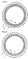
- Figure 1 is a transverse cross-sectional view showing a tube 1 for fuel transportation according to an example of the present invention.
- the tube 1 for fuel transportation has a multilayer structure including five layers: an innermost layer 10 , an adhesive layer 11 , a middle layer 12, an adhesive layer 13, and an outer layer 14 (listed from the inside).
- the tube 1 can be fabricated by the following method.
- Five extruders namely, one for the formation of the innermost layer 10 , one for the formation of the adhesive layer 11 , one for the formation of the middle layer 12 , one for the formation of the adhesive layer 13 , and one for the formation of the outer layer 14 are disposed around a mold.
- Melted resins are extruded by the respective extruders so as to be led through slits in the mold, the resins being layered upon one another. Thereafter, the melted resins are discharged at one end of the mold.
- the melted tube having a five-layer structure is adjusted while being cooled in a sizing bath so as to have predetermined dimensions.
- the present invention encompasses, in addition to the above-described tube 1 having a five-layer structure, a tube 1 for fuel transportation having a multilayer structure including four layers and not including the adhesive layer 13 , as shown in Figure 2 .
- This four-layer tube 1 can be fabricated by the same method by which the tube 1 shown in Figure 1 is fabricated except for using four extruders, instead of five.
- the resins included in the tube are conveniently formed in a temperature range of about 150°C to about 320°C, and more preferably about 190°C to about 280°C.
- the present invention does not intend to provide any particular limitation as to the dimensions of either tube 1 for fuel transportation.
- the preferred thicknesses of the layers may be as follows:
- the preferred thicknesses of the layers may be as follows:
- the tube 1 may have a decreased affinity in conjunction with a joint which follows, thus possibly resulting in the disruption of the inner layer by the joint when the tube 1 is connected thereto or during use of the tube 1 . If the thickness of the inner layer 10 is larger than the larger of the above-mentioned ranges, the flexibility of the entire tube 1 may decrease, and the fabrication cost may increase.
- the thickness of the adhesive layer 11 is smaller than the above-mentioned range, it may be difficult to conduct stable molding of the tube 1 , resulting in nonuniform thickness of the respective layers. This may result in nonuniform adhesion between the layers. If the thickness of the adhesive layer 11 is larger than the above-mentioned range, the thicknesses of the innermost layer 10 , the middle layer 12 , and the outer layer 14 should generally be decreased in order to obtain a tube having a predetermined diameter and a predetermined thickness, thus resulting in deviation from the intended tube characteristics according to the present invention.
- the thickness of the middle layer 12 is smaller than the above-mentioned range, sufficient barrier action against fuels may not be obtained. If the thickness of the middle layer 12 is larger than the above-mentioned range, the flexibility of the entire tube 1 may decrease, and the shock resistance of the tube 1 may decrease.
- the thickness of the adhesive layer 13 is smaller than the above-mentioned range, it becomes difficult to conduct stable molding of the tube 1 , leading to nonuniform thickness of the respective layers. This may result in nonuniform adhesion between the layers. If the thickness of the adhesive layer 13 is larger than the above-mentioned range, the thicknesses of the innermost layer 10, the middle layer 12, and the outer layer 14 should generally be decreased in order to obtain a tube having a predetermined diameter and a predetermined thickness, thus resulting in deviation from the intended tube characteristics according to the present invention.
- the weather resistance of the tube 1 may decrease.
- the inner layers of the tube 1 may be left vulnerable to impacts from stones flying from the outside, and the entire tube 1 may have insufficient resistance against chemical agents (e.g. antifreezing agents, antirust agents, etc.).
- the thickness of the outer layer 14 is larger than the larger of the above-mentioned range, the thicknesses of the innermost layer 10 and the middle layer 12 should be decreased in order to obtain a tube having a predetermined diameter and a predetermined thickness, thus resulting in deviation from the intended tube characteristics according to the present invention.
- the innermost layer 10 the adhesive layer 11, the middle layer 12, the adhesive layer 13 , and the outer layer 14 will be described individually.
- Fluorine type resins e.g. fluorocarbon type resins
- polyamide type resins can be used for the innermost layer 10 .
- the thickness of the innermost layer 10 should preferably account for 5% to 30% of the total thickness of the tube 1 for fuel transportation.
- Fluorine type resins themselves have good corrosion resistance and chemical resistance. Moreover, they have excellent non water-absorbance, friction resistance, non-adhesiveness, self-lubrication, heat resistance, cold resistance, weather resistance, and the like.
- polytetrafluoroethylene has a melt viscosity of 10 3 to 10 12 poise at 380°C, and has poor thermoplastic properties, although categorized as a thermoplastic resin. Therefore, the usual melt molding technique cannot be used for polytetrafluoroethylene.
- fluorine type resins that are thermoplastic and applicable to an extrusion processing are preferably used for the tube for fuel transportation according to the present invention.
- fluorine type resins include: polyvinylidene fluoride resin (hereinafter referred to as PVDF), ethylene-tetrafluoroethylene copolymer resins (hereinafter referred to as ETFE), polyvinyl fluoride resins (hereinafter referred to as PVF), ethylene-chlorotrifluoroethylene copolymer resins (hereinafter referred to as E-CTFE), chlorotrifluoroethylene resins (hereinafter referred to as PCTFE), tetrafluoroethylene-hexafluoropropylene copolymers (hereinafter referred to as FEP), tetrafluoroethylene-perfluoroalcoxyethylene copolymers (hereinafter referred to as PFA), and tetrafluoroethylenehexafluoropropylene-perfluoro
- PVDFs and ETFEs are especially preferable in view of their molding facility and adhesion to other resins.
- a PVDF as mentioned above, is defined to be a homopolymer of vinylidene fluoride or a copolymer of vinylidene with a monomer which is copolymerizable with vinylidene fluoride.
- monomers that are copolymerizable with vinylidene fluoride include vinyl fluoride, tetrafluoroethylene, trifluorochloroethylene, and hexafluoropropylene.
- ETFEs those in which the molar ratio of ethylene to tetrafluoroethylene is in the range of 30/70 to 60/40 are preferable.
- ETFEs may include copolymers with, if necessary, small amounts of other monomers which are copolymerizable therewith.
- Polyamide type resins that are applicable to the present invention are, preferably, linear polyamides having high molecular weights.
- the polyamide may be a homopolyamide, a copolyamide, or a mixture of a homopolyamide and a copolyamide.
- polyamides examples include homopolyamides, copolyamides, or mixtures of homopolyamides and copolyamides having an amide repetition unit represented by the following Formula I or Formula II: - CO - R 1 - NH - - CO - R 2 - CONH - R 3 - NH where R 1 , R 2 , and R 3 each represent a straight-chain alkylene group.
- those homopolyamides, copolyamides, or mixtures thereof in which the number of amide groups per 100 carbon atoms is in the range of 3 to 30, and more preferably in the range of 4 to 25, are preferable as the polyamide type resins to be used in the present invention.
- Examples of preferred homopolyamides include polycapramide (nylon 6), poly- ⁇ -aminoheptanic acid (nylon 7), poly- ⁇ -aminononane acid (nylon 9), polyundecaneamide (nylon 11), polylaurinelactam (nylon 12), polyethylene diamineadipamide (nylon 2, 6), polytetramethylene adipamide (nylon 4, 6), polyhexamethylene adipamide (nylon 6, 6), polyhexamethylene sebacamide (nylon 6, 10), polyhexamethylene dodecamide (nylon 6, 12), polyoctamethylene adipamide (nylon 8, 6), polydecamethylene adipamide (nylon 10, 6), polydecamethylene sebacamide (nylon 10, 10), and polydodecamethylene dodecamide (nylon 12, 12).
- Examples of preferred copolyamides include: caprolactam/laurinelactam copolymers, caprolactam/hexamethylene diammoniumadipate copolymers, laurinelactam/hexamethylene diammoniumadipate copolymers, hexamethylene diammoniumadipate/hexamethylene diammoniumsebacate copolymers, ethylene diammoniumadipate/hexamethylene diammoniumadipate copolymers, and caprolactam/hexamethylene diammoniumadipate/hexamethylene diammoniumsebacate copolymers.
- plasticizers such as aromatic sulfone amides, p-hydroxybenzoic acids, and esters, elastomer components having low elasticity, and lactams to the above-mentioned polyamide type resins so as to impart flexibility thereto.
- elastomer components include: ionomer resins, modified polyolefin type resins, thermoplastic polyurethanes, polyetherblockamides, polyesterblockamides, polyetheresteramide type elastomers, polyester type elastomers, modified stylene type thermoplastic elastomers, modified acrylic rubbers, and modified ethylene-propylene rubbers.
- ionomer resins modified polyolefin type resins
- thermoplastic polyurethanes polyetherblockamides
- polyesterblockamides polyetheresteramide type elastomers
- polyester type elastomers polyester type elastomers
- modified stylene type thermoplastic elastomers modified acrylic rubbers
- modified ethylene-propylene rubbers modified ethylene-propylene rubbers.
- the elastomers can be used alone or in combination with one another.
- the above-described materials for the innermost layer 10 may, if necessary, include various additives such as antioxidants, colorants, anti-static agents, conductive materials, flame retarders, reinforcers, stabilizers, and processing aids.
- Polybutylene naphthalate resins are used for the middle layer 12 .
- the polybutylene naphthalate resins to be used in the present invention are defined as resins that can be prepared by condensation polymerizing naphthalene dicarboxylic acid or an ester forming derivative thereof with one or more butane diols generally in the presence of a catalyst and under appropriate reaction conditions.
- naphthalene dicarboxylic acids examples include naphthalene-2,6-dicarboxylic acid, naphthalene-2,7-dicarboxylic acid, and naphthalene-1,5-dicarboxylic acid.
- naphthalene dicarboxylic acids can be used.
- ester forming derivatives examples include naphthalene-2,6-dicarboxylic acid methyl.
- a particularly preferable polybutylene naphthalate resin to be used for the present invention is polybutylene naphthalate in which naphthalene-2,6-dicarboxylic acid is used as the naphthalate dicarboxylic acid and in which 1,4 butanediol is used as the alkylene glycol.
- polybutylene naphthalate is particularly preferably used for the middle layer 12 in terms of barrier action, mechanical strength of the tube, molding facility, and the like.
- preferable polybutylene naphthalate resins are those which have an inherent viscosity in the range of 0.9 to 1.5 (the inherent viscosity being measured for a solution of 0.005 g/ml at 35°C with o-chlorophenol used as a solvent, according to ASTM D 2857).
- the polybutylene naphthalate resin may alternatively be a copolymer in which a part of either the naphthalene dicarboxylic acid as a polyester component or butylene glycol is substituted by a third component such as other dicarboxylic acids, oxycarboxylic acids, or dioxy compounds.
- dicarboxylic acids examples include naphthalene dicarboxylic acids, terephthalic acids, isophthalic acids, adipic acids, oxalic acids, and diphenyletherdicarboxylic acid.
- oxycarboxylic acids examples include p-oxybenzoic acids and p-oxyethoxybenzoic acids.
- dioxy compounds include dihydric alcohols such as ethylene glycol, propylene glycol, trimethyl glycol, pentamethylene glycol, hexamethylene glycol, diethylene glycol, bisphenol A and polyalkylene glycols such as polyethylene glycol and polytetramethylene glycol.
- the polybutylene naphthalate resin may, if necessary, melt-include other resins, elastomer components, or compounds having a functional group for improving the adhesion to the other layers, and/or include various additives such as antioxidants, colorants, anti-static agents, flame retarders, reinforcers, stabilizers, and processing aids, as long as the barrier action against fuels of the tube 1 is not reduced.
- the thickness of the middle layer 12 should preferably account for 5% to 20% of the total thickness of the tube 1 for fuel transportation. If the thickness of the middle layer 12 accounts for less than 5% of the total thickness of the tube 1 , the barrier action for fuels decreases. If the thickness of the middle layer 12 accounts for more than 20% of the total thickness of the tube 1 , the flexibility of the entire tube 1 may decrease and the shock resistance of the tube 1 may decrease.
- Polybutylene naphthalate resins have such characteristics that the breaking strength and breaking stretch thereof increase as the thickness thereof decreases.
- the shock resistance and toughness of the tube 1 become satisfactory by prescribing the thickness thereof to be in the above mentioned range.
- the outer layer 14 may be composed of any thermoplastic resin, and the present invention does not intend to provide any further limitation to the material for the outer layer 14 .
- thermoplastic resins such as polyolefin type resins such as polyamide resins, fluorine type resins, polyester resins, polyurethane type elastomers, polyamide type elastomers, polyester type elastomers, polyacetal type resins, polyethylenes, and polypropylenes.
- the total thickness of the tube 1 should account for 5% to 20% of the outer diameter of the tube 1 , and the thickness of the outer layer 14 should account for 50% to 85% of the total thickness of the tube 1 for the following reasons. If the total thickness of the tube 1 is excessively small, as compared with the outer diameter of the tube 1, the tube 1 may buckle when bent, thereby interrupting the flow of any fluid that is transported through the tube 1. Moreover, a joint is generally required in order to connect an end of the tube 1 to another piece of equipment; such a joint requires the tube 1 to have an appropriate thickness.
- the outer layer 14 is required to have such weather resistance, damage-proofness, friction resistance, flexibility, inflammability, colorability, printability, anti-static properties, electrical conductivity, electric insulation, and pressure resistance properties as are appropriate to the particular application of the tube.
- it is applicable to provide a further layer having such properties on the outer layer 14.
- a surface layer composed essentially of a resin having a volume specific resistance of about 10 2 to 10 9 ⁇ •cm may be coated on the outside of the outer layer 14.
- a reinforcement layer composed essentially of synthetic fibers (such as nylon, vinylon, polyester, and aramid) and/or wires may be woven or wrapped on the outside of the outer layer 14.
- a reinforcement layer a coating composed of a rubber tube and/or a thermoplastic elastomer, or to wind a coil tube around the tube 1 so as to prevent the tube 1 from being damaged from flying stones, fire, heat of the external air, and the like.
- the adhesive resin to be used as the adhesive layer 11 in the five-layer tube 1 (shown in Figure 1 ) for fuel transportation or in the four-layer tube 1 (shown in Figure 2 ) for fuel transportation, the present invention does not intend to provide any further limitation, although preferably the adhesive resin should be thermally meltable with the innermost layer 10 and the middle layer 12 during coextrusion.
- the adhesive resin to be used as the adhesive layer 11 between the innermost layer 10 and the middle layer 12 may be, preferably, a melted mixture including at least one compound (A) selected from the group consisting of fluorine type resins, flexible fluorine type resins, and fluorine type rubbers and at least one compound (B) selected from the group consisting of crystalline polyester type resins and polyester type elastomers.
- thermoplastic polyurethanes polyamide type elastomers, modified polyolefins, or the like
- the adhesive resin to be used as the adhesive layer 11 between the innermost layer 10 and the middle layer 12 may be, preferably, one or more kinds of thermoplastic polyurethanes, polyetherblockamides, polyesterblockamides, modified polyolefins, polyester copolymers, and polyester type elastomers.
- a composition obtained by melt-mixing a polyamide type resin and a crystalline polyester type resin and/or a polyester type elastomer may alternatively be used as the adhesive resin.
- a composition obtained by melt-mixing one or more kinds of the above-mentioned adhesive resins may preferably be used.
- a composition obtained by melt-mixing with the use of a so-called miscibilizer containing carboxylic acid group, an acid anhydride, a compound having a (meth)acrylic acid or (meth)acrylic acid ester structure, an epoxy compound including glycidyl group or glycidyl ether group, oxazoline group, isocyanate group, amino group, hydroxyl group, and the like may also be preferably used.
- the mixing ratio between the two adhesive resins should be such that sufficient and uniform adhesion is obtained between the innermost layer 10 and the middle layer 12 .
- the mixing ratio between the compound (A) and the compound (B) should be in the range of 80/20 to 30/70 by volume, a preferably in the range of 70/30 to 30/70 by volume. It is preferable to mix, if at all, any of the above-mentioned thermoplastic polyurethanes, polyamide type elastomers, modified polyolefins, and miscibilizers in a ratio, by volume, of 30% or less based on the mixture.
- the mixing ratio between the polyamide type resin and the crystalline polyester type resin and/or the polyester type elastomer should be in the range of 70/30 to 30/70 by volume, an preferably in the range of 60/40 to 40/60 by volume.
- the thickness of the adhesive layer 11 should preferably account for 2% to 10% of the total thickness of the tube 1.
- the thickness of the adhesive layer 11 accounts for less than 2% of the total thickness of the tube 1, it becomes difficult to conduct stable molding of the tube 1, leading to nonuniform thickness of the respective layers. This may result in nonuniform adhesion between the layers 10 and 12. If the thickness of the adhesive layer 11 accounts for more than 10%, the thicknesses of the innermost layer 10, the middle layer 12, and the outer layer 14 must be decreased in order to obtain a tube having a predetermined diameter and a predetermined thickness, thus resulting in deviation from the intended tube characteristics according to the present invention.
- the adhesive resin to be used as the adhesive layer 13 in the five-layer tube 1 (shown in Figure 1 ) for fuel transportation does not intend to provide any further limitation although preferably the adhesive resin should be thermally meltable with the middle layer 12 and the outer layer 14 during coextrusion.
- the adhesive resin to be used for the adhesive layer 13 may be, for example, one or more kinds of thermoplastic polyurethanes, polyetherblockamides, polyesterblockamides, modified polyolefins, polyester copolymers, and polyester type elastomers.
- the thickness of the adhesive layer 13 should preferably account for 2% to 10% of the total thickness of the tube 1.
- the thickness of the adhesive layer 13 accounts for less than 2% of the total thickness of the tube 1 , it becomes difficult to conduct stable molding of the tube 1 , leading to nonuniform thickness of the respective layers. This may result in nonuniform adhesion between the layers 10 and 12. If the thickness of the adhesive layer 13 accounts for more than 10%, the thicknesses of the innermost layer 10 , the middle layer 12 , and the outer layer 14 must be decreased in order to obtain a tube having a predetermined diameter and a predetermined thickness, thus resulting in deviation from the intended tube characteristics according to the present invention.
- the tube 1 may be configurated as a four-layer tube for fuel transportation.
- the tube for fuel transportation having the above-mentioned multilayer structure may be fabricated by a known coextrusion method, an extrusion coating method, or the like.
- the tube can be efficiently fabricated by a coextrusion method with the use of a plurality of extruders and a tube die for multilayer composites, the number of the extruders corresponding to the configuration of the tube.
- a tube for fuel transportation which includes an innermost layer composed essentially of a fluorine type resin or a polyamide type resin, a middle layer composed essentially of a polybutylene naphthalate resin, and an outer layer composed essentially of a thermoplastic resin, the layers being bonded to form an integral four-layer (in the case no adhesive layer is provided between the middle layer and the outer layer) or five-layer (in the case where an adhesive layer is provided between the innermost layer and the middle layer and another adhesive layer is provided between the middle layer and the outer layer) tube. Further layers may be present depending on the particular application for the tube.
- the resultant tube has, as will be described later with reference to the examples of the present invention, excellent barrier action against fuels and excellent kink-proofness.
- sample liquids I and II were provided in a tube having an outer diameter of 8 mm, an inner diameter of 6 mm, and a length of 1000 mm, and left in an oven heated at 60°C or in an oven heated at 40°C, whereby the temporal decrease in the weight of the sample liquid I or II was obtained.
- the decrease in the weight of either sample liquid was divided by the outer surface area of the tube and was calculated to give a value in the form of g/m 2 /day. The calculated value was defined as the transmission rate.
- Sample liquid I (Fuel C): A mixture of a reagent-class toluene and a reagent-class isooctane mixed at a ratio of 1/1 by volume.
- Sample liquid II A mixture of Fuel C and methanol mixed at a ratio of 85/15 by volume.
- a tube having an outer diameter of 8 mm and an inner diameter of 6 mm was bent in a semi-circle shape, with the radius of the semi-circle being gradually decreased until the tube kinked.
- the value of the radius obtained immediately before the tube kinked was used as an indicator of the kink-proofness of the tube. Accordingly, a tube having a smaller radius obtained immediately before the generation of a kink is regarded to be more kink-proof.
- This tube 1 includes an innermost layer 10 (thickness: 0.2 mm) composed essentially of nylon 11, an adhesive layer 11 (thickness: 0.05 mm) composed essentially of a thermoplastic polyurethane, a middle layer 12 (thickness: 0.1 mm) composed essentially of polybutylene naphthalate, an adhesive layer 13 (thickness: 0.05 mm) composed essentially of a thermoplastic polyurethane, and an outer layer 14 (thickness: 0.6 mm) composed essentially of nylon 11.
- This tube 1 was obtained as follows. Each of nylon 11, polybutylene naphthalate, and a thermoplastic polyurethane was inserted into a corresponding one of three extruders. The nylon 11, the polybutylene naphthalate, and the thermoplastic polyurethane were plasticized while being processed at respective temperature ranges of 220°C to 240°C, 230°C to 250°C, and 190°C to 210°C. Thereafter, a three-material five-layer tube having an outer diameter of 8 mm and an inner diameter of 6 mm was extruded from a three-material five-layer tube die maintained at 245°C.
- This tube 1, according to Example 2 includes an innermost layer 10 (thickness: 0.2 mm) composed essentially of nylon 11, an adhesive layer 11 (thickness: 0.05 mm) composed essentially of a modified polyolefin, a middle layer 12 (thickness: 0.1 mm) composed essentially of polybutylene naphthalate, an adhesive layer 13 (thickness: 0.05 mm) composed essentially of a modified polyolefin, and an outer layer 14 (thickness: 0.6 mm) composed essentially of nylon 11.
- This tube 1 was obtained by the same manner by which the tube 1 of Example 1 was obtained except that the adhesive layers 11 and 13 were formed at a temperature range of 230°C to 240°C.
- This tube 1 includes an innermost layer 10 (thickness: 0.2 mm) composed essentially of nylon 11, an adhesive layer 11 (thickness: 0.05 mm) composed essentially of a mixture of a thermoplastic polyurethane and a polyester type elastomer mixed at a ratio of 5/5 by volume, a middle layer 12 (thickness: 0.1 mm) composed essentially of polybutylene naphthalate, an adhesive layer 13 (thickness: 0.05 mm) composed essentially of a mixture of a thermoplastic polyurethane and a polyester type elastomer mixed at a ratio of 5/5 by volume, and an outer layer 14 (thickness: 0.6 mm) composed essentially of nylon 11.
- This tube 1 was obtained by the same manner by which the tube 1 of Example 1 was obtained except that the adhesive layers 11 and 13 were formed at a temperature range of 210°C to 230°C.
- This tube 1, according to Example 4 includes an innermost layer 10 (thickness: 0.2 mm) composed essentially of nylon 11, an adhesive layer 11 (thickness: 0.05 mm) composed essentially of a mixture of a polyetherblockamide and a polyester type elastomer mixed at a ratio of 5/5 by volume, a middle layer 12 (thickness: 0.1 mm) composed essentially of polybutylene naphthalate, an adhesive layer 13 (thickness: 0.05 mm) composed essentially of a mixture of a polyetherblockamide and a polyester type elastomer mixed at a ratio of 5/5 by volume, and an outer layer 14 (thickness: 0.6 mm) composed essentially of nylon 11.
- This tube 1 was obtained by the same manner by which the tube 1 of Example 1 was obtained except that the adhesive layers 11 and 13 were formed at a temperature range of 230°C to 240°C.
- This tube 1 includes an innermost layer 10 (thickness: 0.2 mm) composed essentially of nylon 11, an adhesive layer 11 (thickness: 0.05 mm) composed essentially of a mixture of nylon 11, polybutylene terephthalate, and a thermoplastic polyurethane mixed at a ratio of 4/4/1 by volume, a middle layer 12 (thickness: 0.1 mm) composed essentially of polybutylene naphthalate, and an outer layer 14 (thickness: 0.65 mm) composed essentially of a polyester type elastomer.
- This tube 1 was obtained as follows. Each of the resins used for the innermost layer 10 , the adhesive layer 11 , the middle layer 12 , and the outer layer 14 was inserted into a corresponding one of four extruders. The resins were plasticized while being processed at respective temperature ranges of 210°C to 240°C, 210°C to 240°C, 230°C to 250°C, and 220°C to 240°C. Thereafter, a four-material four-layer tube having an outer diameter of 8 mm and an inner diameter of 6 mm was extruded from a four-material four-layer tube die maintained at 245°C.
- This tube 1, according to Example 6, includes an innermost layer 10 (thickness: 0.2 mm) composed essentially of nylon 11, an adhesive layer 11 (thickness: 0.05 mm) composed essentially of a mixture of nylon 11, a polyester type elastomer, and a modified polyolefin mixed at a ratio of 5/5/1 by volume, a middle layer 12 (thickness: 0.1 mm) composed essentially of polybutylene naphthalate, an adhesive layer 13 (thickness: 0.05 mm) composed essentially of a mixture of nylon 11, a polyester type elastomer, and a modified polyolefin mixed at a ratio of 5/5/1 by volume, and an outer layer 14 (thickness: 0.6 mm) composed essentially of nylon 11.
- This tube 1 was obtained as follows. Each of nylon 11, polybutylene naphthalate, and a mixture of nylon 11, a polyester type elastomer, and a modified polyolefin mixed at a ratio of 5/5/1 by volume was inserted into a corresponding one of three extruders. The nylon 11, the polybutylene naphthalate, and the mixture of nylon 11, the polyester type elastomer, and the modified polyolefin were plasticized while being processed at respective temperature ranges of 220°C to 240°C, 240°C to 260°C, and 230°C to 250°C. Thereafter, a three-material five-layer tube having an outer diameter of 8 mm and an inner diameter of 6 mm was extruded from a three-material five-layer tube die maintained at 260°C.
- the transmission rate and the kink-proofness were measured for the tubes 1 of Examples 1 to 6.
- the measurement results are shown in Table 1 along with the configurations of the tubes 1.
- a larger transmission rate indicates a lower barrier action against fuels of the tube.
- This tube 1 includes an innermost layer 10 (thickness: 0.1 mm) composed essentially of polyvinylidene fluoride (PVDF), an adhesive layer 11 (thickness: 0.05 mm) composed essentially of a mixture of PVDF, polybutylene terephthalate, and a thermoplastic polyurethane mixed at a ratio of 4/4/1 by volume, a middle layer 12 (thickness: 0.1 mm) composed essentially of polybutylene naphthalate, an adhesive layer 13 (thickness: 0.05 mm) composed essentially of a thermoplastic polyurethane, and an outer layer 14 (thickness: 0.6 mm) composed essentially of nylon 11.
- PVDF polyvinylidene fluoride
- an adhesive layer 11 thickness: 0.05 mm
- a middle layer 12 thickness: 0.1 mm
- an adhesive layer 13 thickness: 0.05 mm
- an outer layer 14 thickness: 0.6 mm
- This tube 1 was obtained as follows. Each of the resins used for the innermost layer 10, the adhesive layer 11 , the middle layer 12 , the adhesive layer 13, and the outer layer 14 was inserted into a corresponding one of five extruders. The resins were plasticized while being processed at respective temperature ranges of 200°C to 220°C, 200°C to 220°C, 230°C to 250°C, 190°C to 210°C, and 220°C to 240°C. Thereafter, a five-material five-layer tube having an outer diameter of 8 mm and an inner diameter of 6 mm was extruded from a five-material five-layer tube die maintained at 245°C.
- This tube 1 includes an innermost layer 10 (thickness: 0.1 mm) composed essentially of a polyvinylidene fluoride-hexafluoropropylene copolymer, an adhesive layer 11 (thickness: 0.05 mm) composed essentially of a flexible fluorine type resin, a polyester type elastomer, and a thermoplastic polyurethane mixed at a ratio of 5/4/1 by volume, a middle layer 12 (thickness: 0.1 mm) composed essentially of polybutylene naphthalate, an adhesive layer 13 (thickness: 0.05 mm) composed essentially of a thermoplastic polyurethane, and an outer layer 14 (thickness: 0.7 mm) composed essentially of nylon 11 .
- This tube 1 was obtained by the same manner by which the tube 1 of Example 7 was obtained except that the innermost layer 10 was formed at a temperature range of 190°C to 210°C.
- This tube 1 includes an innermost layer 10 (thickness: 0.1 mm) composed essentially of an ethylene-tetrafluoroethylene copolymer (ETFE), an adhesive layer 11 (thickness: 0.05 mm) composed essentially of a flexible fluorine type resin, a polyester type elastomer, and a modified polyolefin mixed at a ratio of 2/5/3 by volume, a middle layer 12 (thickness: 0.1 mm) composed essentially of polybutylene naphthalate, and an outer layer 14 (thickness: 0.75 mm) composed essentially of a polyester type elastomer.
- an innermost layer 10 thickness: 0.1 mm
- ETFE ethylene-tetrafluoroethylene copolymer
- an adhesive layer 11 thickness: 0.05 mm
- a middle layer 12 thickness: 0.1 mm
- an outer layer 14 thickness: 0.75 mm
- This tube 1 was obtained by using four extruders and a four-material four-layer tube die as in Example 5, the innermost layer 10 and the adhesive layer 11 being formed at respective temperature ranges of 230°C to 260°C and 220°C to 240°C, and maintaining the tube die at 250°C. Thus, the four-material four-layer tube 1 was obtained.
- This tube 1 includes an innermost layer 10 (thickness: 0.1 mm) composed essentially of an ethylene-tetrafluoroethylene copolymer (ETFE), an adhesive layer 11 (thickness: 0.05 mm) composed essentially of ETFE, polybutylene terephthalate, and ethyleneglycidyl methacrylate mixed at a ratio of 5/5/1 by volume, a middle layer 12 (thickness: 0.1 mm) composed essentially of polybutylene naphthalate, an adhesive layer 13 (thickness: 0.05 mm) composed essentially of nylon 11, a polyester type elastomer, and a modified polyolefin mixed at a ratio of 5/5/1 by volume, and an outer layer 14 (thickness: 0.6 mm) composed essentially of nylon 11.
- an innermost layer 10 thickness: 0.1 mm
- ETFE ethylene-tetrafluoroethylene copolymer
- an adhesive layer 11 thickness: 0.05 mm
- a middle layer 12
- This tube 1 was obtained as follows. Each of the resins used for the innermost layer 10 , the adhesive layer 11 , the middle layer 12 , the adhesive layer 13 , and the outer layer 14 was inserted into a corresponding one of five extruders. The resins were plasticized while being processed at respective temperature ranges of 270°C to 290°C, 250°C to 270°C, 240°C to 260°C, 230°C to 250°C, and 220°C to 240°C. Thereafter, a five-material five-layer tube having an outer diameter of 8 mm and an inner diameter of 6 mm was extruded from a five-material five-layer tube die maintained at 260°C.
- the transmission rate and the kink-proofness were measured for the tubes 1 of Examples 7 to 10. The measurement results are shown in Table 2 along with the configurations of the tubes 1 .
- the tube of Comparative Example 1 is a single layer tube (thickness: 1 mm) composed essentially of nylon 11.
- the tube of Comparative Example 2 is a single layer tube (thickness: 1 mm) composed essentially of PVDF.
- the tube of Comparative Example 3 is a single layer tube (thickness: 1 mm) composed essentially of ETFE.
- the tube of Comparative Example 4 is a single layer tube (thickness: 1 mm) composed essentially of a polybutylene terephthalate resin.
- the tube of Comparative Example 5 is a single layer tube (thickness: 1 mm) composed essentially of a polyethylene terephthalate resin.
- the tube of Comparative Example 6 includes an innermost layer 10 (thickness: 0.7 mm) composed essentially of a polybutylene terephthalate resin and an outer layer 14 (thickness: 0.3 mm) composed essentially of nylon 12.
- the tube of Comparative Example 7 is a single layer tube (thickness: 1 mm) composed essentially of cyclohexanedimethanol-ethyleneglycol-terephthalic acid copolymer.
- the tube of Comparative Example 8 includes an innermost layer 10 (thickness: 0.2 mm) composed essentially of nylon 12, a middle layer 12 (thickness: 0.2 mm) composed essentially of polybutylene terephthalate and an outer layer 14 (thickness: 0.6 mm) composed essentially of nylon 12.
- the tube of Comparative Example 9 includes an innermost layer 10 (thickness: 0.1 mm) composed essentially of nylon 12, a middle layer 12 (thickness: 0.15 mm) composed essentially of a mixture of a polybutylene terephthalate resin, nylon 12, and triphenylene phosphite mixed at a ratio of 50/50/0.1 by weight, and an outer layer 14 (thickness: 0.75 mm) composed essentially of nylon 12 .
- the tube of Comparative Example 10 includes an innermost layer 10 (thickness: 0.1 mm) composed essentially of nylon 12, a middle layer 12 (thickness: 0.15 mm) composed essentially of a mixture of a polybutylene terephthalate resin and anhydride maleic acid modified EPM mixed at a ratio of 80/20 by weight, and an outer layer 14 (thickness: 0.75 mm) composed essentially of nylon 12.
- the tube of Comparative Example 11 includes an innermost layer 10 (thickness: 0.2 mm) composed essentially of nylon 12, a middle layer 12 (thickness: 0.2 mm) composed essentially of a mixture of a polybutylene terephthalate resin and an isocyanurate of isophorone diisocyanate mixed at a ratio of 90/10 by weight, and an outer layer 14 (thickness: 0.6 mm) composed essentially of nylon 12.
- the tube of Comparative Example 12 includes an innermost layer 10 (thickness: 0.2 mm) composed essentially of nylon 11, an adhesive layer 11 (thickness: 0.05 mm) composed essentially of a thermoplastic polyurethane, a middle layer 12 (thickness: 0.1 mm) composed essentially of polybutylene terephthalate, an adhesive layer 13 (thickness: 0.05 mm) composed essentially of a thermoplastic polyurethane, and an outer layer 14 (thickness: 0.6 mm) composed essentially of nylon 11.
- the tube of Comparative Example 13 includes an innermost layer 10 (thickness: 0.2 mm) composed essentially of nylon 11, a middle layer 12 (thickness: 0.1 mm) composed essentially of polybutylene naphthalate, and an outer layer 14 (thickness: 0.6 mm) composed essentially of nylon 11.
- the tube of Comparative Example 14 includes an innermost layer 10 (thickness: 0.1 mm) composed essentially of PVDF, an adhesive layer 11 (thickness: 0.05 mm) composed essentially of PVDF, polybutylene terephthalate, and a thermoplastic polyurethane mixed at a ratio of 4/4/1 by volume, a middle layer 12 (thickness: 0.1 mm) composed essentially of polybutylene terephthalate, an adhesive layer 13 (thickness: 0.05 mm) composed essentially of a thermoplastic polyurethane, and an outer layer 14 (thickness: 0.7 mm) composed essentially of nylon 11.
- the tube of Comparative Example 15 includes an innermost layer 10 (thickness: 0.1 mm) composed essentially of PVDF, a middle layer 12 (thickness: 0.1 mm) composed essentially of polybutylene naphthalate, and an outer layer 14 (thickness: 0.8 mm) composed essentially of nylon 11.
- the single tubes of all the Comparative Examples but Comparative Example 13 have a large transmission rate for the fuels, indicative of small barrier action when compared with those of the tubes 1 of Examples 1 to 10 made in accordance with the present invention.
- the common polyester resins used in Comparative Examples 4 to 7 have transmission rates which are several dozen times as large as the transmission rates of the multi-layer tubes 1 according to the present invention incorporating polybutylene naphthalate resins.
- polybutylene naphthalate has remarkably excellent barrier action against fuels.
- the following is apparent from comparison between the tubes 1 of Examples 1 to 6 and the tube of Comparative Example 13.
- the tubes 1 of Examples 1 to 6 and the tube of Comparative Example 13 have only a small difference in barrier action for the fuels.
- the tube of Comparative Example 13 has considerably lower kink-proofness. Accordingly, the kink-proofness of the tubes 1 according to the present invention is remarkably improved by the incorporation of the adhesive layers 11 and 13 .
- the tube of Comparative Example 14 has a large transmission rate for the fuels, indicative of several dozen times smaller barrier action against both Fuel C (Sample liquid I) and the alcohol-containing mixed fuel (Sample liquid II) than the barrier action of the tubes 1 of Example 7.
- polybutylene naphthalate provides far greater advantages than polybutylene terephthalate as a material for the middle layer 12 .
- the tube 1 of Example 7 and the tube of Comparative Example 15 have only a small difference in barrier action against the fuels.
- the tube of Comparative Example 15 has considerably lower kink-proofness.
- the tube of Example 7 has improved kink-proofness. Accordingly, the kink-proofness of the tubes 1 according to the present invention is remarkably improved by the incorporation of the adhesive layers 11 and 13.
Description
- The present invention relates to a tube for transporting fuels, and more particularly to a tube for use as a fuel tube in vehicles such as automobiles.
The tube according to the present invention generally has excellent barriering properties (barrier action) against not only gasoline-based fuels, but also mixed fuels including alcohols, and is kink-proof to an extent that it can be used in a bent state in a relatively small space. - Tubes having a multilayer structure in which a metal pipe, a rubber hose or a single layer tube of nylon, and various resins are layered have conventionally been used as tubes for transporting fuels in a vehicle such as an automobile.
- On the other hand, the realization that it may be difficult to secure an ample supply of gasoline in the future has led to research for substitute fuels in the place of gasoline. As one such substitute fuel, mixed fuels in which alcohols, such as methanol, are added to gasoline have been studied, and have already been put to practical use. Use of methanol as a substitute fuel has attracted much attention because it is expected to provide an improved octane value and contribute to the increased cleanliness of the exhaust gas.
- In particular, for environmental reasons, it is desirable to minimize the amount of fuel to be discharged from a vehicle. This has led to the enforcement of increasingly strict emission regulations. Therefore, tubes are desired which hardly permit fuels to escape therethrough.
- Fuel tubes are often incorporated inside a vehicle body so as to prevent them from being damaged in the impact of a collision and to protect them against flying stones, fire, etc. originating from outside the vehicle. In such cases, it is particularly important substantially to eliminate transmission of gas through the fuel tube because the odor of the transmitted gas might cause discomfort to people in the vehicle, or might even catch fire when the concentration thereof becomes sufficiently high.
- On the other hand, automobile design allows less and less space for tubes to be incorporated, so that it is necessary that the tubes be provided in such a manner as to avoid other equipment in the engine housing.
- Moreover, as is well known, modern vehicles are required to have improved resistance against rust and a reduced weight in view of the demands for increased durability and improved fuel consumption.
- A conventional tube for fuel transportation is disclosed in Japanese Laid-Open Patent Publication No. 4-224384. This tube for fuel transportation is a single layer tube composed of a polyester type resin or alternatively a multilayer tube whose innermost layer is composed of a polyester type resin. In this tube for fuel transportation, polybutylene terephthalate, which has excellent barrier action, is used as the polyester type resin so as to improve the barrier action of the tube.
- German Patent Application Publication-Nos. 4112662, 4137430, 4137431, and 4215608 each disclose a conventional tube for fuel transportation having a multilayer structure including an inner layer and an outer layer composed essentially of polyamide and a middle layer composed of linear crystalline polyester.
- In the above-mentioned Patent Application Publications, it is proposed to form the middle layer of a mixture of linear crystalline polyester and polyamides or compounds having various reactive groups in order to improve the adhesion between the respective layers.
- However, we have found the following drawbacks of a tube for fuel transportation having a multilayer structure including an innermost layer of polybutylene terephthalate:
- i) There is a limit to the improvement of the barrier action against the fuel. Specifically, a fuel for a vehicle, such as an automobile, is generally a mixture of various components. Therefore, a tube may show excellent barrier action for a fuel of one composition but not for a fuel of another composition, thus resulting in insufficient overall barrier action for fuels.
- ii) A tube disclosed in an example of the
above-mentioned Japanese Laid-Open Patent Publication
No. 4-224384, in which the inner layer is composed of
polybutylene terephthalate and the outer layer is
composed of
nylon 12, has poor adhesion between the inner and outer layers, thus resulting in poor kink-proofness. Tubes for fuel transportation of this kind, used for transportation vehicles, are likely to be used in a very small space and bent in a circle with a small radius. Therefore, these tubes are required to be highly kink-proof in order to have practicality. - iii) In cases where a tube for fuel transportation whose innermost layer is composed of a polyester type resin such as polybutylene terephthalate is used for transportation of a mixed fuel including alcohols, the innermost layer may deteriorate through hydrolysis caused by a small amount of moisture contained in the alcohols. Such a tube has the problem of poor durability.
-
- Moreover, an experiment conducted by the inventors of the present invention has revealed the following drawback of a tube for fuel transportation having a multilayer structure including a middle layer composed of a mixture of polybutylene terephthalate and various compounds in order to realize improved adhesion with the polyamide constituting the inner and outer layers: There is a limit to the improvement of the barrier action against fuels. Specifically, as described later with reference to the Comparative Examples, a tube including a middle layer composed of a linear crystalline polyester which is either polybutylene terephthalate or a mixture obtained by mixing polybutylene terephthalate with a polyamide resin, a maleic acid anhydride modified EPM, an ethylene-ethylacrylate-glycidyl methacrylate copolymer, or the like has poor barrier action against fuels although the middle layer is formed of polybutylene terephthalate.
- According to the present invention there is provided a tube for fuel passage comprising an innermost layer comprising a fluorine type resin or polyamide type resin , an intermediate layer comprising a polybutylene naphthalate resin having an inherent viscosity of 0.9 to 1.5, the inherent viscosity being measured for a solution of 0.005 g/ml at 35°C with o-chlorophenol used as a solvent, according to ASTM D 2857, an outer layer comprising a thermoplastic resin or a thermoplastic elastomer, and an adhesive layer between the innermost layer and the intermediate layer.
- In one embodiment of the invention, the thickness of the intermediate layer accounts for 5% to 20% of the total thickness of the tube.
- In still another embodiment of the invention, the innermost layer comprises a polyamide type resin, and the adhesive layer comprises at least one thermoplastic polyurethane, polyetherblockamide, polyesterblockamide, modified polyolefin, polyester copolymer, and/or polyester type elastomer.
- In still another embodiment of the invention, the innermost layer comprises a polyamide type resin, and the adhesive layer comprises an adhesive resin including a polyamide type resin and a crystalline polyester or a thermoplastic polyester elastomer, the polyamide type resin and the crystalline polyester or the thermoplastic polyester elastomer being in the ratio, by volume, in the range of 70/30 to 30/70.
- In still another embodiment of the invention, a miscibilizer, selected from: epoxy compounds having a glycidyl or glycidyl ether group; acid anhydrides; compounds having an oxazoline group, carboxylic acid group, isocyanate group, or a (meth)acrylic acid or (meth)acrylic acid ester structure; and compounds having an amino group or hydroxyl group, is melt-mixed in the adhesive layer.
- In still another embodiment of the invention, the innermost layer comprises a fluorine type resin, and the adhesive layer comprises an adhesive resin comprising at least one fluorine type resin, flexible fluorine type resin, or fluorine type rubber, and at least one crystalline polyester type resin or polyester type elastomer.
- In still another embodiment of the invention, the innermost layer comprises a fluorine type resin, and the adhesive layer comprises an adhesive resin comprising: (A) at least one fluorine type resin, flexible fluorine type resin or fluorine type rubber ; and (B) at least one crystalline polyester type resin or polyester type elastomer, (A) and (B) being in the ratio, by volume, in the range of 80/20 to 20/80.
- The invention described herein makes possible the advantages of (1) providing a tube for fuel transportation which has sufficient barrier action and chemical resistance against current gasoline fuels and substitute fuels, such as mixed fuels including methanol; (2) providing a tube for fuel transportation which has improved kink-proofness and is particularly suitable as a tube for fuel transportation in a vehicle such as an automobile; and (3) providing a tube for fuel transportation which, because the innermost layer comprises a fluorine type resin or a polyamide type resin, has excellent hydrolysis resistance and resistance against fuels and which does not degrade over time, thereby achieving an improved durability as compared with the durability of conventional tubes for fuel transportation.
- Various preferred features and embodiments of the invention will now be described by way of non-limiting example.
- In the accompanying drawings:
- Figure 1 is a transverse cross-sectional view showing a tube for fuel transportation according to one example of the present invention.
- Figure 2 is a transverse cross-sectional view showing a tube for fuel transportation according to another example of the present invention.
-
- Figure 1 is a transverse cross-sectional view showing a
tube 1 for fuel transportation according to an example of the present invention. Thetube 1 for fuel transportation has a multilayer structure including five layers: aninnermost layer 10, anadhesive layer 11, amiddle layer 12, anadhesive layer 13, and an outer layer 14 (listed from the inside). - The
tube 1 can be fabricated by the following method. Five extruders, namely, one for the formation of theinnermost layer 10, one for the formation of theadhesive layer 11, one for the formation of themiddle layer 12, one for the formation of theadhesive layer 13, and one for the formation of theouter layer 14 are disposed around a mold. Melted resins are extruded by the respective extruders so as to be led through slits in the mold, the resins being layered upon one another. Thereafter, the melted resins are discharged at one end of the mold. The melted tube having a five-layer structure is adjusted while being cooled in a sizing bath so as to have predetermined dimensions. - The present invention encompasses, in addition to the above-described
tube 1 having a five-layer structure, atube 1 for fuel transportation having a multilayer structure including four layers and not including theadhesive layer 13, as shown in Figure 2. This four-layer tube 1 can be fabricated by the same method by which thetube 1 shown in Figure 1 is fabricated except for using four extruders, instead of five. - The resins included in the tube are conveniently formed in a temperature range of about 150°C to about 320°C, and more preferably about 190°C to about 280°C.
- The present invention does not intend to provide any particular limitation as to the dimensions of either
tube 1 for fuel transportation. For example, in the case of fabricating a tube for fuel transportation having a multilayer structure including five layers and having an outer diameter of 8 mm and an inner diameter of 6 mm, the tube for fuel transportation being for use in an automobile, the preferred thicknesses of the layers may be as follows: - the innermost layer 10: 0.1 to 0.3 mm,
- the adhesive layer 11: 0.02 to 0.1 mm,
- the middle layer 12: 0.05 to 0.2 mm,
- the adhesive layer 13: 0.02 to 0.1 mm, and
- the outer layer 14: 0.3 to 0.8 mm.
-
- In the case of fabricating a tube for fuel transportation having a multilayer structure including fours layers and having an outer diameter of 8 mm and an inner diameter of 6 mm, the tube for fuel transportation being for use in an automobile, the preferred thicknesses of the layers may be as follows:
- the innermost layer 10: 0.05 to 0.2 mm,
- the adhesive layer 11: 0.02 to 0.1 mm,
- the middle layer 12: 0.05 to 0.2 mm, and
- the outer layer 14: 0.5 to 0.85 mm.
-
- If the thickness of the
inner layer 10 is smaller than the above-mentioned ranges, thetube 1 may have a decreased affinity in conjunction with a joint which follows, thus possibly resulting in the disruption of the inner layer by the joint when thetube 1 is connected thereto or during use of thetube 1. If the thickness of theinner layer 10 is larger than the larger of the above-mentioned ranges, the flexibility of theentire tube 1 may decrease, and the fabrication cost may increase. - If the thickness of the
adhesive layer 11 is smaller than the above-mentioned range, it may be difficult to conduct stable molding of thetube 1, resulting in nonuniform thickness of the respective layers. This may result in nonuniform adhesion between the layers. If the thickness of theadhesive layer 11 is larger than the above-mentioned range, the thicknesses of theinnermost layer 10, themiddle layer 12, and theouter layer 14 should generally be decreased in order to obtain a tube having a predetermined diameter and a predetermined thickness, thus resulting in deviation from the intended tube characteristics according to the present invention. - If the thickness of the
middle layer 12 is smaller than the above-mentioned range, sufficient barrier action against fuels may not be obtained. If the thickness of themiddle layer 12 is larger than the above-mentioned range, the flexibility of theentire tube 1 may decrease, and the shock resistance of thetube 1 may decrease. - If the thickness of the
adhesive layer 13 is smaller than the above-mentioned range, it becomes difficult to conduct stable molding of thetube 1, leading to nonuniform thickness of the respective layers. This may result in nonuniform adhesion between the layers. If the thickness of theadhesive layer 13 is larger than the above-mentioned range, the thicknesses of theinnermost layer 10, themiddle layer 12, and theouter layer 14 should generally be decreased in order to obtain a tube having a predetermined diameter and a predetermined thickness, thus resulting in deviation from the intended tube characteristics according to the present invention. - If the thickness of the
outer layer 14 is smaller than the smaller of the above-mentioned ranges, the weather resistance of thetube 1 may decrease. Moreover, the inner layers of thetube 1 may be left vulnerable to impacts from stones flying from the outside, and theentire tube 1 may have insufficient resistance against chemical agents (e.g. antifreezing agents, antirust agents, etc.). If the thickness of theouter layer 14 is larger than the larger of the above-mentioned range, the thicknesses of theinnermost layer 10 and themiddle layer 12 should be decreased in order to obtain a tube having a predetermined diameter and a predetermined thickness, thus resulting in deviation from the intended tube characteristics according to the present invention. - Hereinafter, the
innermost layer 10, theadhesive layer 11, themiddle layer 12, theadhesive layer 13, and theouter layer 14 will be described individually. - Fluorine type resins (e.g. fluorocarbon type resins) and polyamide type resins can be used for the
innermost layer 10. The thickness of theinnermost layer 10 should preferably account for 5% to 30% of the total thickness of thetube 1 for fuel transportation. - Fluorine type resins (including fluorocarbon resins) themselves have good corrosion resistance and chemical resistance. Moreover, they have excellent non water-absorbance, friction resistance, non-adhesiveness, self-lubrication, heat resistance, cold resistance, weather resistance, and the like.
- Among the fluorine type resins, however, polytetrafluoroethylene has a melt viscosity of 103 to 1012 poise at 380°C, and has poor thermoplastic properties, although categorized as a thermoplastic resin. Therefore, the usual melt molding technique cannot be used for polytetrafluoroethylene.
- Accordingly, fluorine type resins that are thermoplastic and applicable to an extrusion processing are preferably used for the tube for fuel transportation according to the present invention. Examples of such fluorine type resins include: polyvinylidene fluoride resin (hereinafter referred to as PVDF), ethylene-tetrafluoroethylene copolymer resins (hereinafter referred to as ETFE), polyvinyl fluoride resins (hereinafter referred to as PVF), ethylene-chlorotrifluoroethylene copolymer resins (hereinafter referred to as E-CTFE), chlorotrifluoroethylene resins (hereinafter referred to as PCTFE), tetrafluoroethylene-hexafluoropropylene copolymers (hereinafter referred to as FEP), tetrafluoroethylene-perfluoroalcoxyethylene copolymers (hereinafter referred to as PFA), and tetrafluoroethylenehexafluoropropylene-perfluoroalcoxyethylene copolymers (hereinafter referred to as EPA).
- Among the above-mentioned fluorine type resins, PVDFs and ETFEs are especially preferable in view of their molding facility and adhesion to other resins.
- A PVDF, as mentioned above, is defined to be a homopolymer of vinylidene fluoride or a copolymer of vinylidene with a monomer which is copolymerizable with vinylidene fluoride. Examples of monomers that are copolymerizable with vinylidene fluoride include vinyl fluoride, tetrafluoroethylene, trifluorochloroethylene, and hexafluoropropylene.
- As for ETFEs, those in which the molar ratio of ethylene to tetrafluoroethylene is in the range of 30/70 to 60/40 are preferable. ETFEs may include copolymers with, if necessary, small amounts of other monomers which are copolymerizable therewith.
- Polyamide type resins that are applicable to the present invention are, preferably, linear polyamides having high molecular weights. The polyamide may be a homopolyamide, a copolyamide, or a mixture of a homopolyamide and a copolyamide.
- Examples of such polyamides include homopolyamides, copolyamides, or mixtures of homopolyamides and copolyamides having an amide repetition unit represented by the following Formula I or Formula II:
- Herein, in terms of barrier action and fuel resistance for gasoline fuels and mixed fuels containing alcohols, those homopolyamides, copolyamides, or mixtures thereof in which the number of amide groups per 100 carbon atoms is in the range of 3 to 30, and more preferably in the range of 4 to 25, are preferable as the polyamide type resins to be used in the present invention.
- Examples of preferred homopolyamides include polycapramide (nylon 6), poly-ω-aminoheptanic acid (nylon 7), poly-ω-aminononane acid (nylon 9), polyundecaneamide (nylon 11), polylaurinelactam (nylon 12), polyethylene diamineadipamide (nylon 2, 6), polytetramethylene adipamide (nylon 4, 6), polyhexamethylene adipamide (nylon 6, 6), polyhexamethylene sebacamide (nylon 6, 10), polyhexamethylene dodecamide (nylon 6, 12), polyoctamethylene adipamide (nylon 8, 6), polydecamethylene adipamide (
nylon 10, 6), polydecamethylene sebacamide (nylon 10, 10), and polydodecamethylene dodecamide (nylon 12, 12). - Examples of preferred copolyamides include: caprolactam/laurinelactam copolymers, caprolactam/hexamethylene diammoniumadipate copolymers, laurinelactam/hexamethylene diammoniumadipate copolymers, hexamethylene diammoniumadipate/hexamethylene diammoniumsebacate copolymers, ethylene diammoniumadipate/hexamethylene diammoniumadipate copolymers, and caprolactam/hexamethylene diammoniumadipate/hexamethylene diammoniumsebacate copolymers.
- Moreover, it may be convenient to add plasticizers such as aromatic sulfone amides, p-hydroxybenzoic acids, and esters, elastomer components having low elasticity, and lactams to the above-mentioned polyamide type resins so as to impart flexibility thereto.
- Examples of such elastomer components include: ionomer resins, modified polyolefin type resins, thermoplastic polyurethanes, polyetherblockamides, polyesterblockamides, polyetheresteramide type elastomers, polyester type elastomers, modified stylene type thermoplastic elastomers, modified acrylic rubbers, and modified ethylene-propylene rubbers. Among these elastomers components, those which have good compatibility with polyamide type resins and a flexural elasticity of 3000 kgf/cm2 or less are preferable. The elastomers can be used alone or in combination with one another.
- The above-described materials for the
innermost layer 10 may, if necessary, include various additives such as antioxidants, colorants, anti-static agents, conductive materials, flame retarders, reinforcers, stabilizers, and processing aids. - Polybutylene naphthalate resins are used for the
middle layer 12. The polybutylene naphthalate resins to be used in the present invention are defined as resins that can be prepared by condensation polymerizing naphthalene dicarboxylic acid or an ester forming derivative thereof with one or more butane diols generally in the presence of a catalyst and under appropriate reaction conditions. - Examples of such naphthalene dicarboxylic acids include naphthalene-2,6-dicarboxylic acid, naphthalene-2,7-dicarboxylic acid, and naphthalene-1,5-dicarboxylic acid. One or more kinds of these naphthalene dicarboxylic acids can be used.
- Examples of the above-mentioned ester forming derivatives include naphthalene-2,6-dicarboxylic acid methyl.
- A particularly preferable polybutylene naphthalate resin to be used for the present invention is polybutylene naphthalate in which naphthalene-2,6-dicarboxylic acid is used as the naphthalate dicarboxylic acid and in which 1,4 butanediol is used as the alkylene glycol.
- In cases where the
tube 1 for fuel transportation is used as a fuel tube for automobiles, polybutylene naphthalate is particularly preferably used for themiddle layer 12 in terms of barrier action, mechanical strength of the tube, molding facility, and the like. - The strength, resistance against impacts, and stretching properties of a polyalkylene naphthalate resin improve as the viscosity of the polyalkylene naphthalate resin increases. Therefore, preferable polybutylene naphthalate resins are those which have an inherent viscosity in the range of 0.9 to 1.5 (the inherent viscosity being measured for a solution of 0.005 g/ml at 35°C with o-chlorophenol used as a solvent, according to ASTM D 2857).
- Unless the advantages of the
tube 1 for fuel transportation such as the barrier action against fuels are undermined, the polybutylene naphthalate resin may alternatively be a copolymer in which a part of either the naphthalene dicarboxylic acid as a polyester component or butylene glycol is substituted by a third component such as other dicarboxylic acids, oxycarboxylic acids, or dioxy compounds. - Examples of such dicarboxylic acids include naphthalene dicarboxylic acids, terephthalic acids, isophthalic acids, adipic acids, oxalic acids, and diphenyletherdicarboxylic acid.
- Examples of oxycarboxylic acids include p-oxybenzoic acids and p-oxyethoxybenzoic acids.
- Examples of dioxy compounds include dihydric alcohols such as ethylene glycol, propylene glycol, trimethyl glycol, pentamethylene glycol, hexamethylene glycol, diethylene glycol, bisphenol A and polyalkylene glycols such as polyethylene glycol and polytetramethylene glycol.
- The polybutylene naphthalate resin may, if necessary, melt-include other resins, elastomer components, or compounds having a functional group for improving the adhesion to the other layers, and/or include various additives such as antioxidants, colorants, anti-static agents, flame retarders, reinforcers, stabilizers, and processing aids, as long as the barrier action against fuels of the
tube 1 is not reduced. - The thickness of the
middle layer 12 should preferably account for 5% to 20% of the total thickness of thetube 1 for fuel transportation. If the thickness of themiddle layer 12 accounts for less than 5% of the total thickness of thetube 1, the barrier action for fuels decreases. If the thickness of themiddle layer 12 accounts for more than 20% of the total thickness of thetube 1, the flexibility of theentire tube 1 may decrease and the shock resistance of thetube 1 may decrease. - Polybutylene naphthalate resins have such characteristics that the breaking strength and breaking stretch thereof increase as the thickness thereof decreases. The shock resistance and toughness of the
tube 1 become satisfactory by prescribing the thickness thereof to be in the above mentioned range. - In cases where a fluorine type resin or a polyamide type resin is used for the
innermost layer 10 and a polybutylene naphthalate resin is used for themiddle layer 12, as described above, theouter layer 14 may be composed of any thermoplastic resin, and the present invention does not intend to provide any further limitation to the material for theouter layer 14. - Examples of materials for the
outer layer 14 include thermoplastic resins such as polyolefin type resins such as polyamide resins, fluorine type resins, polyester resins, polyurethane type elastomers, polyamide type elastomers, polyester type elastomers, polyacetal type resins, polyethylenes, and polypropylenes. - In cases where the outer diameter of the
tube 1 is 25 mm or less, the total thickness of thetube 1 should account for 5% to 20% of the outer diameter of thetube 1, and the thickness of theouter layer 14 should account for 50% to 85% of the total thickness of thetube 1 for the following reasons. If the total thickness of thetube 1 is excessively small, as compared with the outer diameter of thetube 1, thetube 1 may buckle when bent, thereby interrupting the flow of any fluid that is transported through thetube 1. Moreover, a joint is generally required in order to connect an end of thetube 1 to another piece of equipment; such a joint requires thetube 1 to have an appropriate thickness. - Moreover, the
outer layer 14 is required to have such weather resistance, damage-proofness, friction resistance, flexibility, inflammability, colorability, printability, anti-static properties, electrical conductivity, electric insulation, and pressure resistance properties as are appropriate to the particular application of the tube. In order to impart theouter layer 14 with such properties, it is applicable to provide a further layer having such properties on theouter layer 14. For example, if thetube 1 is required to have anti-static properties, a surface layer composed essentially of a resin having a volume specific resistance of about 102 to 109 Ω•cm may be coated on the outside of theouter layer 14. If thetube 1 is required to have a larger pressure resistance, a reinforcement layer composed essentially of synthetic fibers (such as nylon, vinylon, polyester, and aramid) and/or wires may be woven or wrapped on the outside of theouter layer 14. - Moreover, it may be applicable to provide, as a reinforcement layer, a coating composed of a rubber tube and/or a thermoplastic elastomer, or to wind a coil tube around the
tube 1 so as to prevent thetube 1 from being damaged from flying stones, fire, heat of the external air, and the like. - As for the adhesive resin to be used as the
adhesive layer 11 in the five-layer tube 1 (shown in Figure 1) for fuel transportation or in the four-layer tube 1 (shown in Figure 2) for fuel transportation, the present invention does not intend to provide any further limitation, although preferably the adhesive resin should be thermally meltable with theinnermost layer 10 and themiddle layer 12 during coextrusion. - For example, in cases where the
innermost layer 10 is composed of a fluorine type resin and themiddle layer 12 is composed of a polybutylene naphthalate resin, the adhesive resin to be used as theadhesive layer 11 between theinnermost layer 10 and themiddle layer 12 may be, preferably, a melted mixture including at least one compound (A) selected from the group consisting of fluorine type resins, flexible fluorine type resins, and fluorine type rubbers and at least one compound (B) selected from the group consisting of crystalline polyester type resins and polyester type elastomers. Moreover, in order to obtain a still more uniformly mixed adhesive resin and to increase the adhesive properties thereof, a composition obtained by melt-mixing one or more kinds of thermoplastic polyurethanes, polyamide type elastomers, modified polyolefins, or the like with the above-mentioned melted mixture may preferably be used. A composition obtained by melt-mixing with the use of a so-called miscibilizer containing an epoxy compound including glycidyl group or glycidyl ether group, an acid anhydride, oxazoline group, isocyanate group, carboxylic acid group, amino group, and the like may also be preferably used. - In cases where the
innermost layer 10 is composed of a polyamide type resin and themiddle layer 12 is composed of a polybutylene naphthalate resin, the adhesive resin to be used as theadhesive layer 11 between theinnermost layer 10 and themiddle layer 12 may be, preferably, one or more kinds of thermoplastic polyurethanes, polyetherblockamides, polyesterblockamides, modified polyolefins, polyester copolymers, and polyester type elastomers. - Moreover, a composition obtained by melt-mixing a polyamide type resin and a crystalline polyester type resin and/or a polyester type elastomer may alternatively be used as the adhesive resin. In order to obtain a still more uniformly mixed adhesive resin and to increase the adhesive properties thereof, a composition obtained by melt-mixing one or more kinds of the above-mentioned adhesive resins may preferably be used. A composition obtained by melt-mixing with the use of a so-called miscibilizer containing carboxylic acid group, an acid anhydride, a compound having a (meth)acrylic acid or (meth)acrylic acid ester structure, an epoxy compound including glycidyl group or glycidyl ether group, oxazoline group, isocyanate group, amino group, hydroxyl group, and the like may also be preferably used.
- As for the above-mentioned mixture of two or more kinds of adhesive resins to be used as the
adhesive layer 11, the mixing ratio between the two adhesive resins should be such that sufficient and uniform adhesion is obtained between theinnermost layer 10 and themiddle layer 12. - In the above-mentioned adhesive resins to be used between a fluorine type resin and a polybutylene naphthalate resin, the mixing ratio between the compound (A) and the compound (B) should be in the range of 80/20 to 30/70 by volume, a preferably in the range of 70/30 to 30/70 by volume. It is preferable to mix, if at all, any of the above-mentioned thermoplastic polyurethanes, polyamide type elastomers, modified polyolefins, and miscibilizers in a ratio, by volume, of 30% or less based on the mixture.
- In cases where a polyamide type resin and a crystalline polyester type resin and/or a polyester elastomer is used as the adhesive resin to be used between a polyamide type resin and a polybutylene naphthalate resin, the mixing ratio between the polyamide type resin and the crystalline polyester type resin and/or the polyester type elastomer should be in the range of 70/30 to 30/70 by volume, an preferably in the range of 60/40 to 40/60 by volume. In the case where a miscibilizer is mixed, it is preferable to mix the miscibilizer in a ratio, by volume, of 20% or less based on the mixture.
- Although the present invention does not intend to provide any limitation to the thickness of the
adhesive layer 11 as long as theadhesive layer 11 can function to realize adhesion between theinnermost layer 10 and themiddle layer 12 as described above, the thickness of theadhesive layer 11 should preferably account for 2% to 10% of the total thickness of thetube 1. - If the thickness of the
adhesive layer 11 accounts for less than 2% of the total thickness of thetube 1, it becomes difficult to conduct stable molding of thetube 1, leading to nonuniform thickness of the respective layers. This may result in nonuniform adhesion between thelayers adhesive layer 11 accounts for more than 10%, the thicknesses of theinnermost layer 10, themiddle layer 12, and theouter layer 14 must be decreased in order to obtain a tube having a predetermined diameter and a predetermined thickness, thus resulting in deviation from the intended tube characteristics according to the present invention. - As for the adhesive resin to be used as the
adhesive layer 13 in the five-layer tube 1 (shown in Figure 1) for fuel transportation, the present invention does not intend to provide any further limitation although preferably the adhesive resin should be thermally meltable with themiddle layer 12 and theouter layer 14 during coextrusion. - The adhesive resin to be used for the
adhesive layer 13 may be, for example, one or more kinds of thermoplastic polyurethanes, polyetherblockamides, polyesterblockamides, modified polyolefins, polyester copolymers, and polyester type elastomers. - Although the present invention does not intend to provide any limitation to the thickness of the
adhesive layer 13 as long as theadhesive layer 13 can function to realize adhesion between theinnermost layer 10 and themiddle layer 12 as described above, the thickness of theadhesive layer 13 should preferably account for 2% to 10% of the total thickness of thetube 1. - If the thickness of the
adhesive layer 13 accounts for less than 2% of the total thickness of thetube 1, it becomes difficult to conduct stable molding of thetube 1, leading to nonuniform thickness of the respective layers. This may result in nonuniform adhesion between thelayers adhesive layer 13 accounts for more than 10%, the thicknesses of theinnermost layer 10, themiddle layer 12, and theouter layer 14 must be decreased in order to obtain a tube having a predetermined diameter and a predetermined thickness, thus resulting in deviation from the intended tube characteristics according to the present invention. - In cases where the
middle layer 12 and theouter layer 14 can themselves be thermally melted with each other, there is no need to incorporate theadhesive layer 13 therebetween, and thetube 1 may be configurated as a four-layer tube for fuel transportation. - The tube for fuel transportation having the above-mentioned multilayer structure may be fabricated by a known coextrusion method, an extrusion coating method, or the like. For example, the tube can be efficiently fabricated by a coextrusion method with the use of a plurality of extruders and a tube die for multilayer composites, the number of the extruders corresponding to the configuration of the tube.
- By such a molding method, a tube for fuel transportation can be obtained which includes an innermost layer composed essentially of a fluorine type resin or a polyamide type resin, a middle layer composed essentially of a polybutylene naphthalate resin, and an outer layer composed essentially of a thermoplastic resin, the layers being bonded to form an integral four-layer (in the case no adhesive layer is provided between the middle layer and the outer layer) or five-layer (in the case where an adhesive layer is provided between the innermost layer and the middle layer and another adhesive layer is provided between the middle layer and the outer layer) tube. Further layers may be present depending on the particular application for the tube. The resultant tube has, as will be described later with reference to the examples of the present invention, excellent barrier action against fuels and excellent kink-proofness.
- Hereinafter, illustrative embodiments of the present invention will be described by way of non-limiting example.
- The transmission rate and the kink-proofness of the tubes obtained in the following examples and comparative examples were evaluated by the following methods.
- The following sample liquids I and II were provided in a tube having an outer diameter of 8 mm, an inner diameter of 6 mm, and a length of 1000 mm, and left in an oven heated at 60°C or in an oven heated at 40°C, whereby the temporal decrease in the weight of the sample liquid I or II was obtained. The decrease in the weight of either sample liquid was divided by the outer surface area of the tube and was calculated to give a value in the form of g/m2/day. The calculated value was defined as the transmission rate.
- Sample liquid I (Fuel C): A mixture of a reagent-class toluene and a reagent-class isooctane mixed at a ratio of 1/1 by volume.
- Sample liquid II: A mixture of Fuel C and methanol mixed at a ratio of 85/15 by volume.
- A tube having an outer diameter of 8 mm and an inner diameter of 6 mm was bent in a semi-circle shape, with the radius of the semi-circle being gradually decreased until the tube kinked. The value of the radius obtained immediately before the tube kinked was used as an indicator of the kink-proofness of the tube. Accordingly, a tube having a smaller radius obtained immediately before the generation of a kink is regarded to be more kink-proof.
- This
tube 1, according to Example 1, includes an innermost layer 10 (thickness: 0.2 mm) composed essentially ofnylon 11, an adhesive layer 11 (thickness: 0.05 mm) composed essentially of a thermoplastic polyurethane, a middle layer 12 (thickness: 0.1 mm) composed essentially of polybutylene naphthalate, an adhesive layer 13 (thickness: 0.05 mm) composed essentially of a thermoplastic polyurethane, and an outer layer 14 (thickness: 0.6 mm) composed essentially ofnylon 11. - This
tube 1 was obtained as follows. Each ofnylon 11, polybutylene naphthalate, and a thermoplastic polyurethane was inserted into a corresponding one of three extruders. Thenylon 11, the polybutylene naphthalate, and the thermoplastic polyurethane were plasticized while being processed at respective temperature ranges of 220°C to 240°C, 230°C to 250°C, and 190°C to 210°C. Thereafter, a three-material five-layer tube having an outer diameter of 8 mm and an inner diameter of 6 mm was extruded from a three-material five-layer tube die maintained at 245°C. - This
tube 1, according to Example 2, includes an innermost layer 10 (thickness: 0.2 mm) composed essentially ofnylon 11, an adhesive layer 11 (thickness: 0.05 mm) composed essentially of a modified polyolefin, a middle layer 12 (thickness: 0.1 mm) composed essentially of polybutylene naphthalate, an adhesive layer 13 (thickness: 0.05 mm) composed essentially of a modified polyolefin, and an outer layer 14 (thickness: 0.6 mm) composed essentially ofnylon 11. - This
tube 1 was obtained by the same manner by which thetube 1 of Example 1 was obtained except that theadhesive layers - This
tube 1, according to Example 3, includes an innermost layer 10 (thickness: 0.2 mm) composed essentially ofnylon 11, an adhesive layer 11 (thickness: 0.05 mm) composed essentially of a mixture of a thermoplastic polyurethane and a polyester type elastomer mixed at a ratio of 5/5 by volume, a middle layer 12 (thickness: 0.1 mm) composed essentially of polybutylene naphthalate, an adhesive layer 13 (thickness: 0.05 mm) composed essentially of a mixture of a thermoplastic polyurethane and a polyester type elastomer mixed at a ratio of 5/5 by volume, and an outer layer 14 (thickness: 0.6 mm) composed essentially ofnylon 11. - This
tube 1 was obtained by the same manner by which thetube 1 of Example 1 was obtained except that theadhesive layers - This
tube 1, according to Example 4, includes an innermost layer 10 (thickness: 0.2 mm) composed essentially ofnylon 11, an adhesive layer 11 (thickness: 0.05 mm) composed essentially of a mixture of a polyetherblockamide and a polyester type elastomer mixed at a ratio of 5/5 by volume, a middle layer 12 (thickness: 0.1 mm) composed essentially of polybutylene naphthalate, an adhesive layer 13 (thickness: 0.05 mm) composed essentially of a mixture of a polyetherblockamide and a polyester type elastomer mixed at a ratio of 5/5 by volume, and an outer layer 14 (thickness: 0.6 mm) composed essentially ofnylon 11. - This
tube 1 was obtained by the same manner by which thetube 1 of Example 1 was obtained except that theadhesive layers - This
tube 1, according to Example 5, includes an innermost layer 10 (thickness: 0.2 mm) composed essentially ofnylon 11, an adhesive layer 11 (thickness: 0.05 mm) composed essentially of a mixture ofnylon 11, polybutylene terephthalate, and a thermoplastic polyurethane mixed at a ratio of 4/4/1 by volume, a middle layer 12 (thickness: 0.1 mm) composed essentially of polybutylene naphthalate, and an outer layer 14 (thickness: 0.65 mm) composed essentially of a polyester type elastomer. - This
tube 1 was obtained as follows. Each of the resins used for theinnermost layer 10, theadhesive layer 11, themiddle layer 12, and theouter layer 14 was inserted into a corresponding one of four extruders. The resins were plasticized while being processed at respective temperature ranges of 210°C to 240°C, 210°C to 240°C, 230°C to 250°C, and 220°C to 240°C. Thereafter, a four-material four-layer tube having an outer diameter of 8 mm and an inner diameter of 6 mm was extruded from a four-material four-layer tube die maintained at 245°C. - This
tube 1, according to Example 6, includes an innermost layer 10 (thickness: 0.2 mm) composed essentially ofnylon 11, an adhesive layer 11 (thickness: 0.05 mm) composed essentially of a mixture ofnylon 11, a polyester type elastomer, and a modified polyolefin mixed at a ratio of 5/5/1 by volume, a middle layer 12 (thickness: 0.1 mm) composed essentially of polybutylene naphthalate, an adhesive layer 13 (thickness: 0.05 mm) composed essentially of a mixture ofnylon 11, a polyester type elastomer, and a modified polyolefin mixed at a ratio of 5/5/1 by volume, and an outer layer 14 (thickness: 0.6 mm) composed essentially ofnylon 11. - This
tube 1 was obtained as follows. Each ofnylon 11, polybutylene naphthalate, and a mixture ofnylon 11, a polyester type elastomer, and a modified polyolefin mixed at a ratio of 5/5/1 by volume was inserted into a corresponding one of three extruders. Thenylon 11, the polybutylene naphthalate, and the mixture ofnylon 11, the polyester type elastomer, and the modified polyolefin were plasticized while being processed at respective temperature ranges of 220°C to 240°C, 240°C to 260°C, and 230°C to 250°C. Thereafter, a three-material five-layer tube having an outer diameter of 8 mm and an inner diameter of 6 mm was extruded from a three-material five-layer tube die maintained at 260°C. - The transmission rate and the kink-proofness were measured for the
tubes 1 of Examples 1 to 6. The measurement results are shown in Table 1 along with the configurations of thetubes 1. A larger transmission rate indicates a lower barrier action against fuels of the tube.
- This
tube 1, according to Example 7, includes an innermost layer 10 (thickness: 0.1 mm) composed essentially of polyvinylidene fluoride (PVDF), an adhesive layer 11 (thickness: 0.05 mm) composed essentially of a mixture of PVDF, polybutylene terephthalate, and a thermoplastic polyurethane mixed at a ratio of 4/4/1 by volume, a middle layer 12 (thickness: 0.1 mm) composed essentially of polybutylene naphthalate, an adhesive layer 13 (thickness: 0.05 mm) composed essentially of a thermoplastic polyurethane, and an outer layer 14 (thickness: 0.6 mm) composed essentially ofnylon 11. - This
tube 1 was obtained as follows. Each of the resins used for theinnermost layer 10, theadhesive layer 11, themiddle layer 12, theadhesive layer 13, and theouter layer 14 was inserted into a corresponding one of five extruders. The resins were plasticized while being processed at respective temperature ranges of 200°C to 220°C, 200°C to 220°C, 230°C to 250°C, 190°C to 210°C, and 220°C to 240°C. Thereafter, a five-material five-layer tube having an outer diameter of 8 mm and an inner diameter of 6 mm was extruded from a five-material five-layer tube die maintained at 245°C. - This
tube 1, according to Example 8, includes an innermost layer 10 (thickness: 0.1 mm) composed essentially of a polyvinylidene fluoride-hexafluoropropylene copolymer, an adhesive layer 11 (thickness: 0.05 mm) composed essentially of a flexible fluorine type resin, a polyester type elastomer, and a thermoplastic polyurethane mixed at a ratio of 5/4/1 by volume, a middle layer 12 (thickness: 0.1 mm) composed essentially of polybutylene naphthalate, an adhesive layer 13 (thickness: 0.05 mm) composed essentially of a thermoplastic polyurethane, and an outer layer 14 (thickness: 0.7 mm) composed essentially ofnylon 11. - This
tube 1 was obtained by the same manner by which thetube 1 of Example 7 was obtained except that theinnermost layer 10 was formed at a temperature range of 190°C to 210°C. - This
tube 1, according to Example 9, includes an innermost layer 10 (thickness: 0.1 mm) composed essentially of an ethylene-tetrafluoroethylene copolymer (ETFE), an adhesive layer 11 (thickness: 0.05 mm) composed essentially of a flexible fluorine type resin, a polyester type elastomer, and a modified polyolefin mixed at a ratio of 2/5/3 by volume, a middle layer 12 (thickness: 0.1 mm) composed essentially of polybutylene naphthalate, and an outer layer 14 (thickness: 0.75 mm) composed essentially of a polyester type elastomer. - This
tube 1 was obtained by using four extruders and a four-material four-layer tube die as in Example 5, theinnermost layer 10 and theadhesive layer 11 being formed at respective temperature ranges of 230°C to 260°C and 220°C to 240°C, and maintaining the tube die at 250°C. Thus, the four-material four-layer tube 1 was obtained. - This
tube 1, according to Example 10, includes an innermost layer 10 (thickness: 0.1 mm) composed essentially of an ethylene-tetrafluoroethylene copolymer (ETFE), an adhesive layer 11 (thickness: 0.05 mm) composed essentially of ETFE, polybutylene terephthalate, and ethyleneglycidyl methacrylate mixed at a ratio of 5/5/1 by volume, a middle layer 12 (thickness: 0.1 mm) composed essentially of polybutylene naphthalate, an adhesive layer 13 (thickness: 0.05 mm) composed essentially ofnylon 11, a polyester type elastomer, and a modified polyolefin mixed at a ratio of 5/5/1 by volume, and an outer layer 14 (thickness: 0.6 mm) composed essentially ofnylon 11. - This
tube 1 was obtained as follows. Each of the resins used for theinnermost layer 10, theadhesive layer 11, themiddle layer 12, theadhesive layer 13, and theouter layer 14 was inserted into a corresponding one of five extruders. The resins were plasticized while being processed at respective temperature ranges of 270°C to 290°C, 250°C to 270°C, 240°C to 260°C, 230°C to 250°C, and 220°C to 240°C. Thereafter, a five-material five-layer tube having an outer diameter of 8 mm and an inner diameter of 6 mm was extruded from a five-material five-layer tube die maintained at 260°C. - The transmission rate and the kink-proofness were measured for the
tubes 1 of Examples 7 to 10. The measurement results are shown in Table 2 along with the configurations of thetubes 1.
- The tube of Comparative Example 1 is a single layer tube (thickness: 1 mm) composed essentially of
nylon 11. - The tube of Comparative Example 2 is a single layer tube (thickness: 1 mm) composed essentially of PVDF.
- The tube of Comparative Example 3 is a single layer tube (thickness: 1 mm) composed essentially of ETFE.
- The tube of Comparative Example 4 is a single layer tube (thickness: 1 mm) composed essentially of a polybutylene terephthalate resin.
- The tube of Comparative Example 5 is a single layer tube (thickness: 1 mm) composed essentially of a polyethylene terephthalate resin.
- The tube of Comparative Example 6 includes an innermost layer 10 (thickness: 0.7 mm) composed essentially of a polybutylene terephthalate resin and an outer layer 14 (thickness: 0.3 mm) composed essentially of
nylon 12. - The tube of Comparative Example 7 is a single layer tube (thickness: 1 mm) composed essentially of cyclohexanedimethanol-ethyleneglycol-terephthalic acid copolymer.
- The tube of Comparative Example 8 includes an innermost layer 10 (thickness: 0.2 mm) composed essentially of
nylon 12, a middle layer 12 (thickness: 0.2 mm) composed essentially of polybutylene terephthalate and an outer layer 14 (thickness: 0.6 mm) composed essentially ofnylon 12. - The tube of Comparative Example 9 includes an innermost layer 10 (thickness: 0.1 mm) composed essentially of
nylon 12, a middle layer 12 (thickness: 0.15 mm) composed essentially of a mixture of a polybutylene terephthalate resin,nylon 12, and triphenylene phosphite mixed at a ratio of 50/50/0.1 by weight, and an outer layer 14 (thickness: 0.75 mm) composed essentially ofnylon 12. - The tube of Comparative Example 10 includes an innermost layer 10 (thickness: 0.1 mm) composed essentially of
nylon 12, a middle layer 12 (thickness: 0.15 mm) composed essentially of a mixture of a polybutylene terephthalate resin and anhydride maleic acid modified EPM mixed at a ratio of 80/20 by weight, and an outer layer 14 (thickness: 0.75 mm) composed essentially ofnylon 12. - The tube of Comparative Example 11 includes an innermost layer 10 (thickness: 0.2 mm) composed essentially of
nylon 12, a middle layer 12 (thickness: 0.2 mm) composed essentially of a mixture of a polybutylene terephthalate resin and an isocyanurate of isophorone diisocyanate mixed at a ratio of 90/10 by weight, and an outer layer 14 (thickness: 0.6 mm) composed essentially ofnylon 12. - The tube of Comparative Example 12 includes an innermost layer 10 (thickness: 0.2 mm) composed essentially of
nylon 11, an adhesive layer 11 (thickness: 0.05 mm) composed essentially of a thermoplastic polyurethane, a middle layer 12 (thickness: 0.1 mm) composed essentially of polybutylene terephthalate, an adhesive layer 13 (thickness: 0.05 mm) composed essentially of a thermoplastic polyurethane, and an outer layer 14 (thickness: 0.6 mm) composed essentially ofnylon 11. - The tube of Comparative Example 13 includes an innermost layer 10 (thickness: 0.2 mm) composed essentially of
nylon 11, a middle layer 12 (thickness: 0.1 mm) composed essentially of polybutylene naphthalate, and an outer layer 14 (thickness: 0.6 mm) composed essentially ofnylon 11. - The tube of Comparative Example 14 includes an innermost layer 10 (thickness: 0.1 mm) composed essentially of PVDF, an adhesive layer 11 (thickness: 0.05 mm) composed essentially of PVDF, polybutylene terephthalate, and a thermoplastic polyurethane mixed at a ratio of 4/4/1 by volume, a middle layer 12 (thickness: 0.1 mm) composed essentially of polybutylene terephthalate, an adhesive layer 13 (thickness: 0.05 mm) composed essentially of a thermoplastic polyurethane, and an outer layer 14 (thickness: 0.7 mm) composed essentially of
nylon 11. - The tube of Comparative Example 15 includes an innermost layer 10 (thickness: 0.1 mm) composed essentially of PVDF, a middle layer 12 (thickness: 0.1 mm) composed essentially of polybutylene naphthalate, and an outer layer 14 (thickness: 0.8 mm) composed essentially of
nylon 11. - The transmission rate and the kink-proofness were measured for the tubes of Comparative Examples 1 to 15. The measurement results are shown in Table 3 and 4 along with the configurations of the tubes.


- Hereinafter, the barrier action and kink-proofness of the
tubes 1 of Examples 1 to 10 will be compared with those of the tubes of Comparative Examples 1 to 15, with reference to Tables 1 to 4. - As seen from Tables 1, 2, and 3, the single tubes of all the Comparative Examples but Comparative Example 13 have a large transmission rate for the fuels, indicative of small barrier action when compared with those of the
tubes 1 of Examples 1 to 10 made in accordance with the present invention. In particular, the common polyester resins used in Comparative Examples 4 to 7 have transmission rates which are several dozen times as large as the transmission rates of themulti-layer tubes 1 according to the present invention incorporating polybutylene naphthalate resins. As will be appreciated, polybutylene naphthalate has remarkably excellent barrier action against fuels. - The following is apparent from comparison between the
tube 1 of Example 1 and the tube of Comparative Example 12. The tube of Comparative Example 12, although highly kink-proof owing to the presence of theadhesive layers middle layer 12. - The following is apparent from comparison between the
tubes 1 of Examples 1 to 6 and the tube of Comparative Example 13. Thetubes 1 of Examples 1 to 6 and the tube of Comparative Example 13 have only a small difference in barrier action for the fuels. However, the tube of Comparative Example 13 has considerably lower kink-proofness. Accordingly, the kink-proofness of thetubes 1 according to the present invention is remarkably improved by the incorporation of theadhesive layers - The following is apparent from comparison between the
tube 1 of Example 7 and the tube of Comparative Example 14. The tube of Comparative Example 14 has a large transmission rate for the fuels, indicative of several dozen times smaller barrier action against both Fuel C (Sample liquid I) and the alcohol-containing mixed fuel (Sample liquid II) than the barrier action of thetubes 1 of Example 7. As will be appreciated, polybutylene naphthalate provides far greater advantages than polybutylene terephthalate as a material for themiddle layer 12. - The following is apparent from comparison between the
tube 1 of Example 7 and the tube of Comparative Example 15. Thetube 1 of Example 7 and the tube of Comparative Example 15 have only a small difference in barrier action against the fuels. However, the tube of Comparative Example 15 has considerably lower kink-proofness. On the other hand, the tube of Example 7 has improved kink-proofness. Accordingly, the kink-proofness of thetubes 1 according to the present invention is remarkably improved by the incorporation of theadhesive layers
Claims (8)
- A tube for fuel passage comprising:an innermost layer comprising a fluorine type resin or polyamide type resinan intermediate layer comprising a polybutylene naphthalate resin having an inherent viscosity of 0.9 to 1.5, the inherent viscosity being measured for a solution of 0.005 g/ml at 35°C with o-chlorophenol used as a solvent, according to ASTM D 2857,an outer layer comprising a thermoplastic resin or a thermoplastic elastomer, andan adhesive layer between the innermost layer and the intermediate layer.
- A tube according to claim 1
wherein the thickness of the intermediate layer is 5% to 20% of a total thickness of the tube wall. - A tube according to claim 1 or claim 2
wherein the innermost layer comprises a polyamide type resin, and
wherein the adhesive layer comprises at least one material selected from thermoplastic polyurethanes, polyetherblockamides, polyesterblockamides, modified polyolefins, polyester copolymers, and polyester type elastomers. - A tube according to claim 1 or claim 2
wherein the innermost layer comprises a polyamide type resin, and
wherein the adhesive layer comprises an adhesive resin comprising a polyamide type resin and a crystalline polyester or a thermoplastic polyester elastomer, the polyamide type resin and the crystalline polyester or the thermoplastic polyester elastomer being in a ratio, by volume, in the range of 70/30 to 30/70. - A tube according to claim 4,
wherein a miscibilizer, selected from: epoxy compounds having a glycidyl or glycidyl ether group; acid anhydrides; compounds having an oxazoline group, carboxylic acid group, isocyanate group, or a (meth)acrylic acid or (meth)acrylic acid ester structure; and compounds having an amino group or hydroxyl group, is melt-mixed in the adhesive layer. - A tube according to claim 1 or claim 2
wherein the innermost layer comprises a fluorine type resin, and
wherein the adhesive layer comprises an adhesive resin comprising at least one selected from fluorine type resins, flexible fluorine type resins, and fluorine type rubbers, and at least one selected from crystalline polyester type resins and polyester type elastomers. - A tube according to claim 1 or claim 2,
wherein the innermost layer comprises a fluorine type resin, and
wherein the adhesive layer comprises an adhesive resin comprising: (A) at least one selected from fluorine type resins, flexible fluorine type resins, and fluorine type rubbers; and (B) at least one selected from crystalline polyester type resins and polyester type elastomers, (A) and (B) being in the ratio, by volume, in the range of 80/20 to 20/80. - A tube according to claim 6 or claim 7,
wherein a miscibilizer, selected from: epoxy compounds having a glycidyl or glycidyl ether group; acid anhydrides; compounds having an oxazoline group, carboxylic acid group, isocyanate group, or a (meth)acrylic acid or (meth)acrylic acid ester structure; and compounds having an amino group or hydroxyl group, is melt-mixed in the adhesive layer.
Applications Claiming Priority (3)
| Application Number | Priority Date | Filing Date | Title |
|---|---|---|---|
| JP19261093 | 1993-08-03 | ||
| JP19261093 | 1993-08-03 | ||
| JP192610/93 | 1993-08-03 |
Publications (2)
| Publication Number | Publication Date |
|---|---|
| EP0637509A1 EP0637509A1 (en) | 1995-02-08 |
| EP0637509B1 true EP0637509B1 (en) | 2002-10-23 |
Family
ID=16294128
Family Applications (1)
| Application Number | Title | Priority Date | Filing Date |
|---|---|---|---|
| EP94305715A Expired - Lifetime EP0637509B1 (en) | 1993-08-03 | 1994-08-02 | A tube for fuel transportation |
Country Status (4)
| Country | Link |
|---|---|
| US (2) | US6089278A (en) |
| EP (1) | EP0637509B1 (en) |
| KR (1) | KR100303858B1 (en) |
| DE (1) | DE69431579T2 (en) |
Cited By (3)
| Publication number | Priority date | Publication date | Assignee | Title |
|---|---|---|---|---|
| US7691470B2 (en) | 2001-03-05 | 2010-04-06 | 3Form | Laminate structure with polycarbonate sheets |
| US8157942B1 (en) | 2007-05-08 | 2012-04-17 | Willham John E C | Multivariate color system with texture application |
| EP3299174B1 (en) * | 2015-05-20 | 2022-02-16 | Hakko Corporation | Ink supply tube |
Families Citing this family (76)
| Publication number | Priority date | Publication date | Assignee | Title |
|---|---|---|---|---|
| US6378562B1 (en) * | 1992-04-14 | 2002-04-30 | Itt Industries, Inc. | Multi-layer tubing having electrostatic dissipation for handling hydrocarbon fluids |
| EP0637509B1 (en) * | 1993-08-03 | 2002-10-23 | Nitta Moore Company | A tube for fuel transportation |
| MX9603600A (en) * | 1994-03-04 | 1997-05-31 | Aeroquip Corp | Composite and tie layer therefor. |
| DE4418006A1 (en) | 1994-05-21 | 1995-11-23 | Huels Chemische Werke Ag | Multilayer plastic pipe with good layer adhesion |
| DE19507025A1 (en) * | 1995-03-01 | 1996-09-05 | Huels Chemische Werke Ag | Multi-layer pipe with an electrically conductive inner layer |
| JP3390952B2 (en) * | 1995-06-26 | 2003-03-31 | ネクストロム・ホールデイング・ソシエテ・アノニム | Extruders and methods, tubular products, and tubes |
| DE19535489C2 (en) * | 1995-09-23 | 2003-08-21 | Cooper Standard Automotive D | Flexible cooling water pipe for motor vehicles |
| DE19537003A1 (en) * | 1995-10-04 | 1997-04-10 | Inventa Ag | Adhesion promoter based on polyamide |
| US5891373A (en) * | 1996-05-23 | 1999-04-06 | Eagle-Picher Industries, Inc. | Process of making a multi-layer tube |
| US5778942A (en) * | 1996-07-01 | 1998-07-14 | Stanley Aviation Corporation | Vehicle including freeze stress resistant fluid conducting apparatuses |
| EP0949996A2 (en) * | 1996-12-31 | 1999-10-20 | The Dow Chemical Company | Laminate structures for fuel containers |
| US6279614B1 (en) | 1997-03-29 | 2001-08-28 | Hewing Gmbh | Multi-layer plastic tube |
| US6432542B1 (en) * | 1997-11-06 | 2002-08-13 | Alliedsignal Inc. | Multicomponent structures having improved adhesion |
| US6555190B1 (en) | 1997-11-06 | 2003-04-29 | Honeywell International Inc. | Films with UV blocking characteristics |
| US6156400A (en) * | 1998-04-09 | 2000-12-05 | 3M Innovative Properties Company | Multi-layer compositions comprising a fluoropolymer |
| US6096428A (en) * | 1998-04-09 | 2000-08-01 | 3M Innovative Properties Company | Multi-layer compositions comprising a fluoropolymer |
| DE19831898B4 (en) * | 1998-07-16 | 2004-01-22 | Rasmussen Gmbh | Fluid line for fuels and fuel vapors |
| DE19838709A1 (en) * | 1998-08-26 | 2000-03-02 | Degussa | Multi-layer composite with barrier effect |
| JP2000154890A (en) * | 1998-11-18 | 2000-06-06 | Tokai Rubber Ind Ltd | Tube for fuel pipe |
| FR2794837B1 (en) * | 1999-06-10 | 2001-08-10 | Atofina | TUBE FOR THE TRANSPORT OF FUEL |
| US6279615B1 (en) * | 1999-09-03 | 2001-08-28 | Tokai Rubber Industries, Ltd. | Fuel hose |
| FR2812929B1 (en) * | 2000-08-11 | 2004-01-09 | Nobel Plastiques | MULTILAYER PLASTIC TUBE FOR FLUIDS USED IN MOTOR VEHICLES |
| JP2002156075A (en) * | 2000-09-05 | 2002-05-31 | Tokai Rubber Ind Ltd | Fuel hose |
| DE10057990A1 (en) * | 2000-11-23 | 2002-06-06 | Rasmussen Gmbh | Multilayer pipe |
| US7008700B1 (en) | 2001-03-05 | 2006-03-07 | 3-Form | Architectural laminate panel with embedded compressible objects and methods for making the same |
| US6776195B2 (en) * | 2001-03-26 | 2004-08-17 | Parker-Hannifin Corporation | Tubular polymeric composites for tubing and hose constructions |
| ES2220839T3 (en) * | 2001-04-10 | 2004-12-16 | Rasmussen Gmbh | MULTI-PIPE TUBE FOR HYDROCARBON FLUIDS. |
| EP1249654A1 (en) * | 2001-04-12 | 2002-10-16 | Rasmussen GmbH | Multilayer tube |
| JP2003033983A (en) * | 2001-05-15 | 2003-02-04 | Tokai Rubber Ind Ltd | Fuel hose |
| JPWO2003008850A1 (en) | 2001-07-19 | 2004-11-11 | ニッタ・ムアー株式会社 | Heat resistant resin tube |
| US6591871B2 (en) * | 2001-09-13 | 2003-07-15 | Dayco Products, Llc | Low permeation polybutylene terephthalate and polybutylene naphthalate fuel and vapor tubes |
| FR2832781B1 (en) * | 2001-11-27 | 2004-04-16 | Nobel Plastiques | MULTI-LAYERED PIPE FOR THE TRANSPORT OF AUTOMOTIVE FLUIDS |
| JP2003287164A (en) * | 2002-01-24 | 2003-10-10 | Tokai Rubber Ind Ltd | Fuel hose |
| JP2003287165A (en) * | 2002-01-24 | 2003-10-10 | Tokai Rubber Ind Ltd | Fuel hose |
| DE10203626B4 (en) * | 2002-01-30 | 2004-01-08 | Veritas Ag | Multi-layer pipe or hose |
| US20030145896A1 (en) * | 2002-02-06 | 2003-08-07 | Saint-Gobain Performance Plastics Corporation | Coiled laminated air brake tubing |
| FR2838501B1 (en) * | 2002-04-15 | 2005-07-01 | Nobel Plastiques | TUBE FOR TRANSPORTING A MOTOR FLUID |
| JP3606280B2 (en) * | 2002-07-16 | 2005-01-05 | 日産自動車株式会社 | Resin tubes and fuel piping tubes |
| US6659512B1 (en) * | 2002-07-18 | 2003-12-09 | Hewlett-Packard Development Company, L.P. | Integrated circuit package employing flip-chip technology and method of assembly |
| JP2004090405A (en) * | 2002-08-30 | 2004-03-25 | Tokai Rubber Ind Ltd | Hose for automobile fuel system |
| FR2845453B1 (en) * | 2002-10-07 | 2004-11-26 | Nobel Plastiques | PIPELINE FOR THE TRANSPORT OF HYDROGEN-CONTAINING FLUIDS |
| JP2004169851A (en) * | 2002-11-21 | 2004-06-17 | Sanoh Industrial Co Ltd | Multi-layered tube |
| JP2004239429A (en) * | 2003-01-16 | 2004-08-26 | Tokai Rubber Ind Ltd | Fuel system hose for automobile |
| US6880862B2 (en) * | 2003-04-10 | 2005-04-19 | Dayco Products, Llc | Conductive tubular insert for a fuel transport system, and method |
| CN100560358C (en) * | 2003-05-12 | 2009-11-18 | 大金工业株式会社 | Laminate |
| JP2005081663A (en) * | 2003-09-08 | 2005-03-31 | Nissan Motor Co Ltd | Resin tube and tube for fuel system piping |
| ES2527663T3 (en) * | 2004-01-29 | 2015-01-28 | TI Automotive (Fuldabrück) GmbH | Multilayer synthetic tube with barrier properties |
| TW200538472A (en) | 2004-04-13 | 2005-12-01 | Daikin Ind Ltd | The component of fluid transporter |
| JP4582091B2 (en) | 2004-04-13 | 2010-11-17 | ダイキン工業株式会社 | Chlorotrifluoroethylene copolymer |
| US20060046017A1 (en) | 2004-09-01 | 2006-03-02 | 3Form | Architectural glass panels with embedded objects and methods for making the same |
| FR2874987B1 (en) * | 2004-09-08 | 2006-12-01 | Nobel Plastiques Soc Par Actio | MULTICOUCHE PIPING PA / PO-PA / TPE-E |
| FR2875169B1 (en) * | 2004-09-15 | 2008-07-04 | Arkema Sa | STRUCTURE COMPRISING AT LEAST ONE POLYETHYLENE LAYER AND AT LEAST ONE BARRIER POLYMER LAYER |
| US20060057391A1 (en) * | 2004-09-15 | 2006-03-16 | Anthony Bonnet | Structure comprising at least one polyethylene layer and at least one layer of barrier polymer |
| DE102004048777A1 (en) | 2004-10-07 | 2006-04-13 | Degussa Ag | Multi-layer composite with polyester layer and protective layer |
| JP4562510B2 (en) * | 2004-12-10 | 2010-10-13 | 三桜工業株式会社 | Multi-layer resin tube |
| FR2879281B1 (en) * | 2004-12-13 | 2007-02-16 | Nobel Plastiques Soc Par Actio | MODIFIED FLUOROPOLYMER / EVOH / PA TUBE |
| FR2886708B1 (en) * | 2005-06-02 | 2007-08-17 | Arkema Sa | USE OF MODIFIED FLUORINE POLYMER FOR THE TRANSPORT OF WATER OR GAS |
| JP2007261078A (en) * | 2006-03-28 | 2007-10-11 | Tokai Rubber Ind Ltd | Hose for fuel |
| FR2904867B1 (en) * | 2006-08-08 | 2008-09-19 | Arkema France | MULTILAYER TUBE FOR TRANSPORTING WATER OR GAS |
| FR2918067B1 (en) * | 2007-06-27 | 2011-07-01 | Arkema France | COMPOSITE MATERIAL COMPRISING DISPERSED NANOTUBES IN A FLUORINATED POLYMERIC MATRIX. |
| JP4450018B2 (en) | 2007-06-28 | 2010-04-14 | 日産自動車株式会社 | Multilayer hose |
| US7866348B2 (en) * | 2008-05-01 | 2011-01-11 | Saint-Gobain Performance Plastics Corporation | Multi-layered fuel tubing |
| BE1018516A3 (en) * | 2009-03-30 | 2011-02-01 | Tekni Plex Europ Nv Nv | METHOD FOR MANUFACTURING A MULTI-LAYER FLUOR POLYMER FILM STRUCTURE, AND A FILM STRUCTURE MANUFACTURED IN THIS WAY, AND ITS USE IN THE PHOTOVOLTABLE APPLICATIONS. |
| JP5551379B2 (en) * | 2009-03-31 | 2014-07-16 | 帝人株式会社 | Thermoplastic materials for automotive fuel parts |
| USD691289S1 (en) | 2012-09-05 | 2013-10-08 | 3Form, Inc. | Panel with cut and aligned thatch interlayer |
| WO2014047627A1 (en) * | 2012-09-24 | 2014-03-27 | Eaton Corporation | Air brake tubing and compositions for making the same |
| DE202012104423U1 (en) * | 2012-11-16 | 2014-02-17 | Rehau Ag + Co. | Flexible hose with a multi-layered wall |
| EP2772354B1 (en) * | 2013-03-01 | 2018-12-05 | TI Automotive (Fuldabrück) GmbH | Multilayer fuel pipe |
| KR20150046790A (en) * | 2013-09-24 | 2015-05-04 | 한일튜브 주식회사 | Hydrogen transfer tube |
| JP2016089810A (en) * | 2014-11-11 | 2016-05-23 | 株式会社デンソー | Fuel supply device |
| EP3069874B1 (en) * | 2015-03-17 | 2017-07-19 | Evonik Degussa GmbH | Laminate with one polyester layer |
| EP3069875B1 (en) * | 2015-03-17 | 2017-07-05 | Evonik Degussa GmbH | Multilayer compound with one fluoropolymer layer |
| WO2017141901A1 (en) * | 2016-02-19 | 2017-08-24 | 株式会社八興 | Static electricity dissipating resin hose |
| US10316992B2 (en) * | 2017-06-09 | 2019-06-11 | GM Global Technology Operations LLC | Tubing for fluid cooling systems |
| EP3530454B1 (en) * | 2018-02-22 | 2020-06-10 | TI Automotive (Fuldabrück) GmbH | Multilayer motor vehicle pipeline |
| EP3875263A1 (en) * | 2020-03-06 | 2021-09-08 | TI Automotive (Fuldabrück) GmbH | Tube construct |
Family Cites Families (23)
| Publication number | Priority date | Publication date | Assignee | Title |
|---|---|---|---|---|
| FR2479528A1 (en) | 1980-03-26 | 1981-10-02 | Gefitec Sa | PERFECTED VIDEO CASSETTE |
| DE3613188A1 (en) * | 1985-04-19 | 1986-10-23 | Toyoda Gosei Co., Ltd., Haruhi, Aichi | RUBBER LAMINATE |
| US4800129A (en) * | 1987-03-26 | 1989-01-24 | E. I. Du Pont De Nemours And Company | Multi-layer plastic container |
| JPH01159245A (en) * | 1987-12-16 | 1989-06-22 | Tokai Rubber Ind Ltd | Rubber hose |
| EP0336806A3 (en) * | 1988-03-21 | 1991-02-27 | Alcatel N.V. | Simultaneous extrusion of a dual-layer buffer tube |
| JPH0733878B2 (en) * | 1989-05-29 | 1995-04-12 | 東海ゴム工業株式会社 | Refrigerant transport hose |
| DE4001125C1 (en) * | 1989-11-20 | 1990-12-13 | Technoform Caprano + Brunnhofer Kg, 3501 Fuldabrueck, De | |
| DE4010767A1 (en) * | 1990-04-04 | 1991-10-10 | Daimler Benz Ag | IMPACT PROTECTION DEVICE FOR A PASSENGER OF A MOTOR VEHICLE |
| KR0170407B1 (en) * | 1990-09-26 | 1999-03-20 | 모토야마 가즈오 | Gas-and-oil impermeable hose construction |
| JP3136614B2 (en) * | 1990-12-20 | 2001-02-19 | 東海ゴム工業株式会社 | Tubing for fuel piping |
| DE4112662A1 (en) * | 1991-04-18 | 1992-10-22 | Huels Chemische Werke Ag | MULTILAYER PLASTIC PIPE |
| DE4112668A1 (en) * | 1991-04-18 | 1992-10-22 | Huels Chemische Werke Ag | THERMOPLASTIC MULTILAYER COMPOSITION |
| US5170011A (en) * | 1991-09-25 | 1992-12-08 | Teleflex Incorporated | Hose assembly |
| DE4138510A1 (en) * | 1991-11-14 | 1993-05-19 | Huels Chemische Werke Ag | MOLDS CONTAINING A POLYCONDENSATE |
| DE4137430A1 (en) * | 1991-11-14 | 1993-05-19 | Huels Chemische Werke Ag | MULTILAYER PLASTIC PIPE |
| EP0542182B1 (en) * | 1991-11-14 | 1997-02-26 | Hüls Aktiengesellschaft | Thermoplastic laminate |
| DE4137431A1 (en) * | 1991-11-14 | 1993-05-19 | Huels Chemische Werke Ag | MULTILAYER PLASTIC PIPE |
| DE4137434A1 (en) * | 1991-11-14 | 1993-05-19 | Huels Chemische Werke Ag | THERMOPLASTIC MULTILAYER COMPOSITION |
| DE69311403T2 (en) * | 1992-03-05 | 1997-12-04 | Nitta Moore Co Ltd | Fuel transfer pipe |
| JP2578705B2 (en) * | 1992-03-30 | 1997-02-05 | 東海ゴム工業株式会社 | Resin tube for fuel pipe and method of manufacturing the same |
| DE4214383C2 (en) * | 1992-04-30 | 1996-08-14 | Inventa Ag | Coextruded multilayer polymer tube |
| DE4215608A1 (en) * | 1992-05-12 | 1993-11-18 | Huels Chemische Werke Ag | Multi-layer plastic pipe |
| EP0637509B1 (en) * | 1993-08-03 | 2002-10-23 | Nitta Moore Company | A tube for fuel transportation |
-
1994
- 1994-08-02 EP EP94305715A patent/EP0637509B1/en not_active Expired - Lifetime
- 1994-08-02 DE DE69431579T patent/DE69431579T2/en not_active Expired - Lifetime
- 1994-08-03 KR KR1019940019224A patent/KR100303858B1/en not_active IP Right Cessation
-
1996
- 1996-06-18 US US08/665,572 patent/US6089278A/en not_active Expired - Lifetime
-
2000
- 2000-03-21 US US09/532,165 patent/US6355321B1/en not_active Expired - Lifetime
Cited By (7)
| Publication number | Priority date | Publication date | Assignee | Title |
|---|---|---|---|---|
| US7691470B2 (en) | 2001-03-05 | 2010-04-06 | 3Form | Laminate structure with polycarbonate sheets |
| US8157942B1 (en) | 2007-05-08 | 2012-04-17 | Willham John E C | Multivariate color system with texture application |
| US8182903B2 (en) | 2007-05-08 | 2012-05-22 | 3Form, Inc. | Multivariate color system with texture application |
| US8268106B2 (en) | 2007-05-08 | 2012-09-18 | 3Form, Inc. | Multivariate color system with texture application |
| US8617695B2 (en) | 2007-05-08 | 2013-12-31 | 3Form, Inc. | Multivariate color system with texture application |
| US9348065B2 (en) | 2007-05-08 | 2016-05-24 | 3Form, Llc | Multivariate color system with texture application |
| EP3299174B1 (en) * | 2015-05-20 | 2022-02-16 | Hakko Corporation | Ink supply tube |
Also Published As
| Publication number | Publication date |
|---|---|
| DE69431579D1 (en) | 2002-11-28 |
| EP0637509A1 (en) | 1995-02-08 |
| KR100303858B1 (en) | 2001-11-22 |
| DE69431579T2 (en) | 2003-03-27 |
| US6355321B1 (en) | 2002-03-12 |
| KR960007176A (en) | 1996-03-22 |
| US6089278A (en) | 2000-07-18 |
Similar Documents
| Publication | Publication Date | Title |
|---|---|---|
| EP0637509B1 (en) | A tube for fuel transportation | |
| JP3126275B2 (en) | Fuel transfer tube | |
| JP3793249B2 (en) | Multi-layer coolant conduit | |
| EP1002977B1 (en) | Multi-layer fuel and vapor tube | |
| CA2138906C (en) | Blow-molded coolant conduit | |
| US5469892A (en) | Corrugated polymeric tubing having at least three layers with at least two respective layers composed of polymeric materials dissimilar to one another | |
| EP1059478B1 (en) | Multi-layer fuel and vapor tube | |
| JP3701282B2 (en) | Thermoplastic multilayer composite | |
| KR101474059B1 (en) | Low-permeation flexible fuel hose | |
| US5763034A (en) | Fuel transfer tube | |
| US6896005B2 (en) | Multi-layer tubing having electrostatic dissipation for handling hydrocarbon fluids | |
| US5884671A (en) | Multi-layer fuel and vapor tube | |
| EP1186818A1 (en) | Elongated fuel and vapor tube having multiple layers and method of making the same | |
| EP0757767A1 (en) | Multi-layer tubing having electrostatic dissipation for handling hydrocarbon fluids | |
| WO1999041538A1 (en) | Multi-layer tubing having at least one intermediate layer formed from a polyamide alloy | |
| US20040013835A1 (en) | Multilayer plastic tube for fluids used in motor vehicles | |
| JP2000018446A (en) | Multilayer tubular body for cooler hose and its manufacture | |
| EP1076791A2 (en) | Multi-layer filler pipe for vehicle fuel tanks | |
| WO1994009302A1 (en) | Corrugated multilayer tubing having at least two dissimilar polymeric materials | |
| WO2002029298A2 (en) | Convoluted tubing having a non-convoluted inner layer for handling hydrocarbon materials | |
| JPH08247344A (en) | Air brake tube |
Legal Events
| Date | Code | Title | Description |
|---|---|---|---|
| PUAI | Public reference made under article 153(3) epc to a published international application that has entered the european phase |
Free format text: ORIGINAL CODE: 0009012 |
|
| AK | Designated contracting states |
Kind code of ref document: A1 Designated state(s): BE DE FR GB IT |
|
| 17P | Request for examination filed |
Effective date: 19950731 |
|
| 17Q | First examination report despatched |
Effective date: 19990604 |
|
| GRAG | Despatch of communication of intention to grant |
Free format text: ORIGINAL CODE: EPIDOS AGRA |
|
| GRAG | Despatch of communication of intention to grant |
Free format text: ORIGINAL CODE: EPIDOS AGRA |
|
| GRAG | Despatch of communication of intention to grant |
Free format text: ORIGINAL CODE: EPIDOS AGRA |
|
| GRAH | Despatch of communication of intention to grant a patent |
Free format text: ORIGINAL CODE: EPIDOS IGRA |
|
| GRAH | Despatch of communication of intention to grant a patent |
Free format text: ORIGINAL CODE: EPIDOS IGRA |
|
| GRAA | (expected) grant |
Free format text: ORIGINAL CODE: 0009210 |
|
| AK | Designated contracting states |
Kind code of ref document: B1 Designated state(s): BE DE FR GB IT |
|
| REG | Reference to a national code |
Ref country code: GB Ref legal event code: FG4D |
|
| REF | Corresponds to: |
Ref document number: 69431579 Country of ref document: DE Date of ref document: 20021128 |
|
| RAP2 | Party data changed (patent owner data changed or rights of a patent transferred) |
Owner name: NITTA MOORE COMPANY |
|
| ET | Fr: translation filed | ||
| PLBE | No opposition filed within time limit |
Free format text: ORIGINAL CODE: 0009261 |
|
| STAA | Information on the status of an ep patent application or granted ep patent |
Free format text: STATUS: NO OPPOSITION FILED WITHIN TIME LIMIT |
|
| REG | Reference to a national code |
Ref country code: FR Ref legal event code: CA |
|
| 26N | No opposition filed |
Effective date: 20030724 |
|
| PGFP | Annual fee paid to national office [announced via postgrant information from national office to epo] |
Ref country code: DE Payment date: 20130821 Year of fee payment: 20 |
|
| PGFP | Annual fee paid to national office [announced via postgrant information from national office to epo] |
Ref country code: GB Payment date: 20130821 Year of fee payment: 20 Ref country code: FR Payment date: 20130823 Year of fee payment: 20 |
|
| PGFP | Annual fee paid to national office [announced via postgrant information from national office to epo] |
Ref country code: IT Payment date: 20130828 Year of fee payment: 20 |
|
| PGFP | Annual fee paid to national office [announced via postgrant information from national office to epo] |
Ref country code: BE Payment date: 20130823 Year of fee payment: 20 |
|
| REG | Reference to a national code |
Ref country code: DE Ref legal event code: R071 Ref document number: 69431579 Country of ref document: DE |
|
| REG | Reference to a national code |
Ref country code: GB Ref legal event code: PE20 Expiry date: 20140801 |
|
| BE20 | Be: patent expired |
Owner name: *NITTA MOORE CY Effective date: 20140802 |
|
| PG25 | Lapsed in a contracting state [announced via postgrant information from national office to epo] |
Ref country code: DE Free format text: LAPSE BECAUSE OF EXPIRATION OF PROTECTION Effective date: 20140805 |
|
| PG25 | Lapsed in a contracting state [announced via postgrant information from national office to epo] |
Ref country code: GB Free format text: LAPSE BECAUSE OF EXPIRATION OF PROTECTION Effective date: 20140801 |